Display panel driving method, system and display device

A technology of display panel and driving method, applied in static indicators, instruments, etc., can solve problems such as cost increase, inability to reach agreement on impedance in sector area, cost problems, etc., and achieve the effect of improving chromatic aberration and improving optical quality

Active Publication Date: 2017-09-15
HKC CORP LTD +1
View PDF5 Cites 13 Cited by
  • Summary
  • Abstract
  • Description
  • Claims
  • Application Information

AI Technical Summary

Problems solved by technology

[0002] When designing the pixel display matrix of a thin-film transistor liquid crystal display, it is necessary to perform centralized fan-shaped wiring processing on the pressing area of ​​the driver integrated circuit. Because the distance between the output of the driver integrated circuit and each display line is not equal, the impedance of the fan-shaped area cannot be reached. , so that the degree of delay in the voltage change of each display line is different, and finally the charging time on each display line is inconsistent, causing color drift. The greater the difference, the greater the difference in voltage change delay on each display line, and the more serious the color shift
[0003] Traditionally, it is usually used to reduce the difference in trace impedance by changing the material of the display trace, or reduce the number of output channels of the driver integrated circuit, reduce the area of ​​the fan-shaped area, and reduce the difference in the length of the display trace, thereby reducing the trace impedance. However, changing the material of the display wiring requires the support of the TFT-LCD process, and the transformation of the process and the problems related to the process yield will cause a huge cost problem, and the reduction of the number of output channels of the driver integrated circuit will be corresponding Increasing the number of driving integrated circuits will lead to an increase in cost, so the traditional method of improving color shift is costly

Method used


Image

  • Display panel driving method, system and display device
  • Display panel driving method, system and display device
  • Display panel driving method, system and display device

Examples


Embodiment Construction

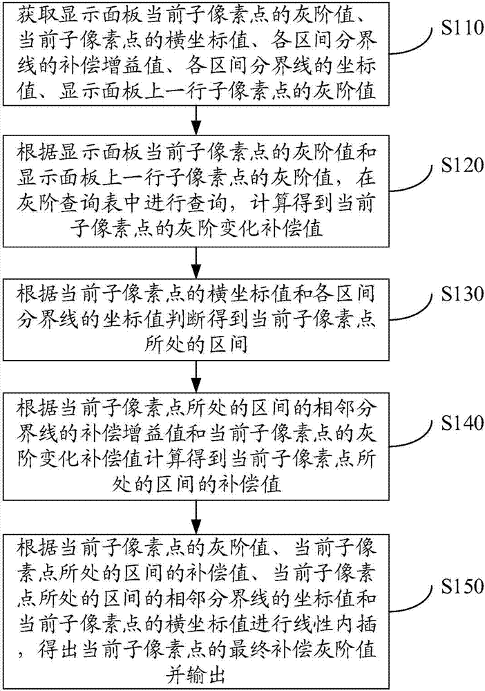
[0025] In one embodiment, such as figure 1 As shown, a display panel driving method includes the following steps:

[0026] Step S110: Obtain the gray scale value of the current sub-pixel point of the display panel, the abscissa value of the current sub-pixel point, the compensation gain value of the boundary line of each interval, the coordinate value of the boundary line of each interval, and the grayscale value of a row of sub-pixel points on the display panel. order value.

[0027] Specifically, the compensation gain value of the boundary line of each interval is obtained through debugging and measurement with the actual panel type. The corresponding relationship between a row of sub-pixels on the display panel and the current sub-pixel is that when the grayscale compensation is performed according to the preset order in the preset direction, a compensated sub-pixel is on the current sub-pixel. In this embodiment, the display panel Perform chromatic aberration compensatio...


PUM


Abstract

The invention relates to a display panel driving method, a system and a display device. The method comprises the following steps: acquiring the grayscale value of a current sub pixel of a display panel, the horizontal coordinate value of the current sub pixel, the compensation gain value of each interval boundary line, the coordinate value of each interval boundary line, and the grayscale values of the sub pixels in the previous row of the display panel; querying in a grayscale query table according to the grayscale value of the current sub pixel of the display panel and the grayscale values of the sub pixels in the previous row, and calculating the grayscale change compensation value of the current sub pixel; judging an interval to which the current sub pixel belongs; getting the compensation value of the interval according to the compensation gain values of two boundary lines adjacent to the interval and the grayscale change compensation value of the current sub pixel; and finally, calculating the compensation value of the current sub pixel, and calculating the final compensation grayscale value of the current sub pixel according to the grayscale value of the current sub pixel and the compensation value of the current sub pixel. The chromatic aberration is improved and the optical taste of products is improved without increasing the cost.

Description

technical field [0001] The present invention relates to the field of display panels, in particular to a display panel driving method, system and display device. Background technique [0002] When designing the pixel display matrix of a thin-film transistor liquid crystal display, it is necessary to perform centralized fan-shaped wiring processing on the pressing area of ​​the driver integrated circuit. Because the distance between the output of the driver integrated circuit and each display line is not equal, the impedance of the fan-shaped area cannot be reached. , so that the degree of delay in the voltage change of each display line is different, and finally the charging time on each display line is inconsistent, causing color drift. The greater the difference, the greater the difference in voltage change delay on each display trace, and the more serious the color shift. [0003] Traditionally, it is usually used to reduce the difference in trace impedance by changing th...

Claims


Application Information

Patent Timeline
Patent Type & Authority Applications(China)
IPC IPC(8): G09G3/36
CPCG09G3/3607G09G3/20G09G3/3611G09G2320/0285G09G2340/16G09G2320/0242G09G3/2074G09G2360/16G09G2320/029
Inventor 曾德康
Owner HKC CORP LTD
Why Eureka
Try Eureka