Array substrate, display panel and display device

An array substrate and display area technology, applied in semiconductor devices, electrical components, circuits, etc., can solve the problems of wide left and right borders of the display panel and cannot meet the requirements of narrow borders, and achieve the effect of reducing the area

Active Publication Date: 2017-07-28
SHANGHAI AVIC OPTOELECTRONICS
View PDF5 Cites 7 Cited by
  • Summary
  • Abstract
  • Description
  • Claims
  • Application Information

AI Technical Summary

Problems solved by technology

[0008] In view of this, embodiments of the present invention provide an array substrate, a display panel, and a display device, which solve the problem that the left and right borders of the display panel in the prior art are relatively wide and cannot meet the demand for narrower borders.

Method used


Image

  • Array substrate, display panel and display device
  • Array substrate, display panel and display device
  • Array substrate, display panel and display device

Examples


Embodiment Construction

[0053] In order to better understand the technical solutions of the present invention, the embodiments of the present invention will be described in detail below in conjunction with the accompanying drawings.

[0054] It should be clear that the described embodiments are only some of the embodiments of the present invention, not all of them. Based on the embodiments of the present invention, all other embodiments obtained by persons of ordinary skill in the art without creative efforts fall within the protection scope of the present invention.

[0055]Terms used in the embodiments of the present invention are only for the purpose of describing specific embodiments, and are not intended to limit the present invention. As used in the embodiments of the present invention and the appended claims, the singular forms "a", "said" and "the" are also intended to include the plural forms unless the context clearly indicates otherwise.

[0056] It should be understood that the term "and...


PUM


Abstract

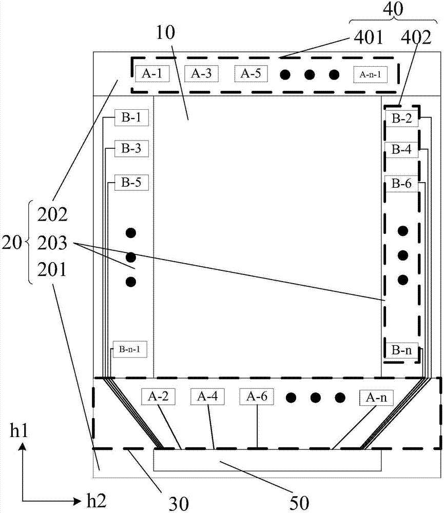
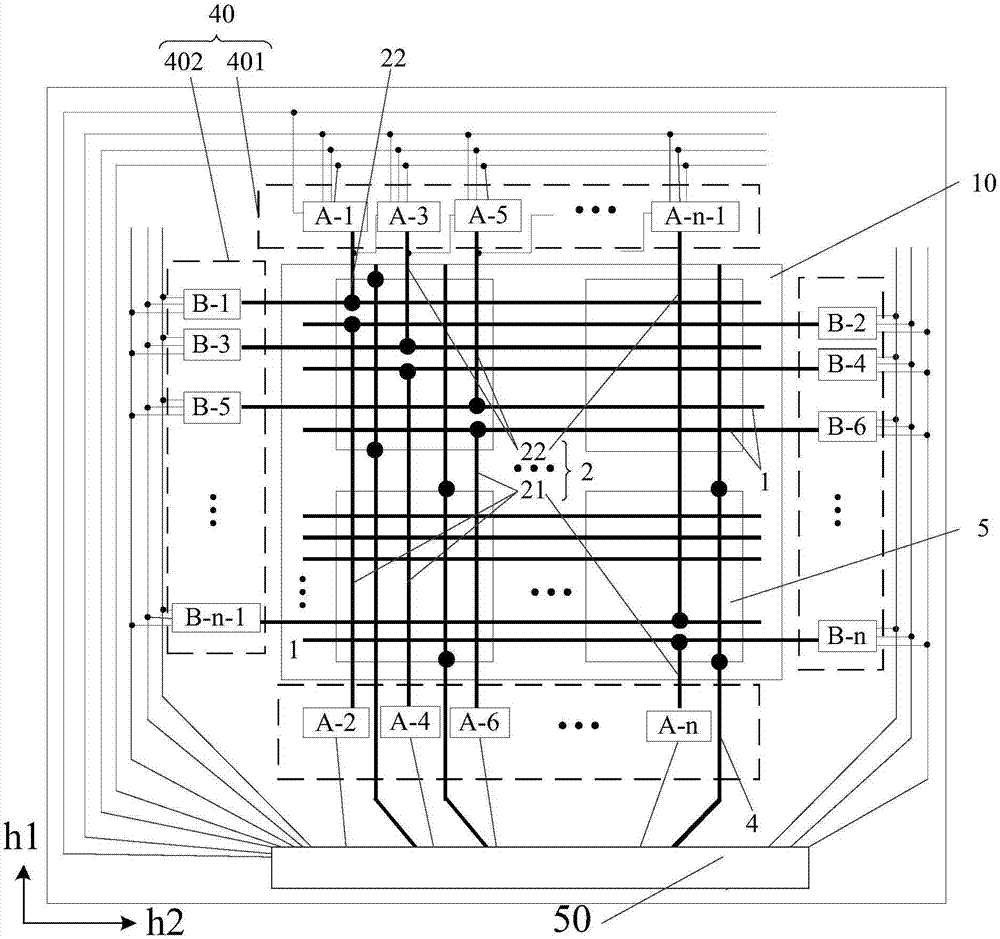
An embodiment of the invention provides an array substrate, a display panel and a display device. The array substrate comprises a display area, a surrounding area surrounding the display area and a grid drive circuit. The surrounding area comprises a first region and a second region arranged oppositely in the grid line arrangement direction, wherein a fan section close to one side of the display area locates in the first region; the grid drive circuit comprises a drive function circuit, wherein the drive function circuit is arranged in the first region and / or the second region; the drive function circuit is connected with grid lines through grid lead wires arranged in the display area; and extension direction of the grid lead wires is same with the grid line arrangement direction. Therefore, the provided technical scheme can, to some extent, solve the problem that since the left and right borders of the display panel are relatively wide in the prior art, narrow border requirement cannot be met.

Description

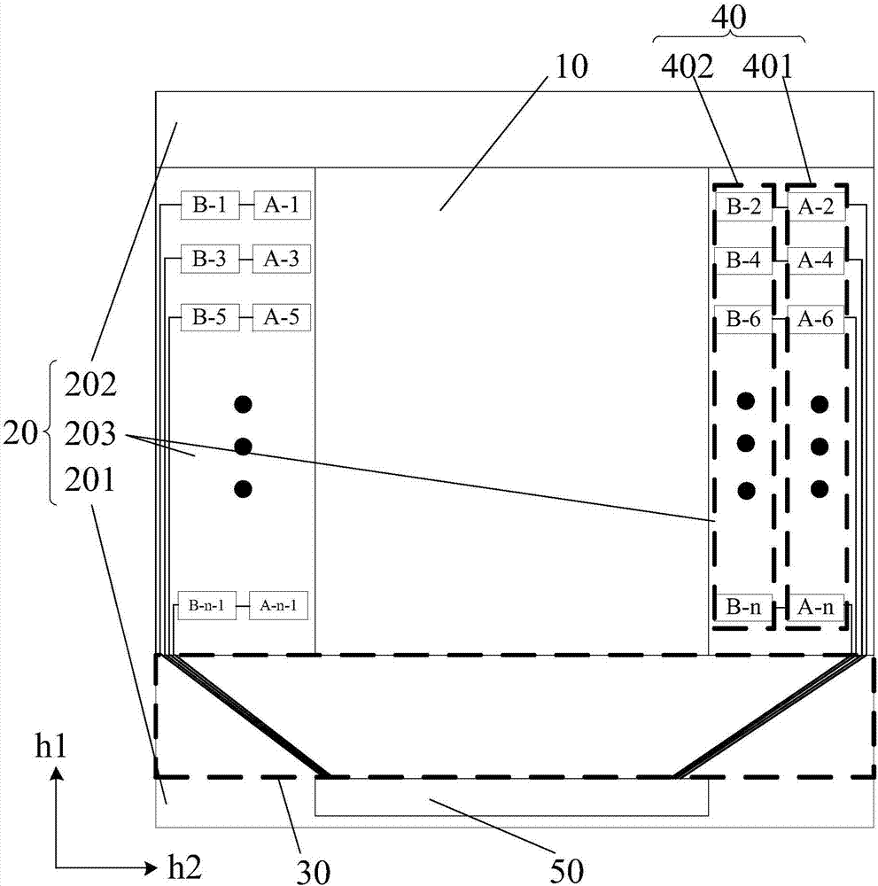
[0001] 【Technical field】 [0002] The present invention relates to the field of display technology, in particular to an array substrate, a display panel and a display device. [0003] 【Background technique】 [0004] Please refer to figure 1 , which is a schematic top view structure of a display panel in the prior art, such as figure 1 As shown, the display panel includes: a display area 10 and a peripheral area 20 arranged around the display area. For the convenience of expression, according to the relative position of the peripheral area 20 relative to the display area 10, the peripheral area 20 can be divided into the following categories: figure 1 The three subregions shown. Wherein, the first region 201 and the second region 202 are arranged opposite to each other in the grid line arrangement direction h1, and the third region 203 is other regions in the peripheral region 20 except the first region 201 and the second region 202, such as figure 1 As shown, the third area ...

Claims


Application Information

Patent Timeline
Patent Type & Authority Applications(China)
IPC IPC(8): H01L27/12
CPCH01L27/124
Inventor 秦锋简守甫夏志强曹兆铿
Owner SHANGHAI AVIC OPTOELECTRONICS
Why Eureka
Try Eureka