


Quick Research
Generate reliable direction feasibility study reports for your R&D in just a few steps.

Technical Q&A
Discover and master advanced knowledge NOW. Basics, ideas, possibilities, all at once.

Find Solutions
As an expert in R&D theories, this can generate solutions to your technical problems instantly.

Evaluate Feasibility
Analyze your overall solution with one click, know your potential R&D risks in advance.

Monitor Landscape
Get weekly tech updates, stay abreast of the latest tech innovations and key insights.
Pump insert
A technology of inserts and stagnation points, which can be used in pump components, pumps, engine components, etc., and can solve problems such as the complex structure of the pump pressure plate
- Summary
- Abstract
- Description
- Claims
- Application Information
AI Technical Summary
Problems solved by technology
Method used
Image

Examples
Embodiment Construction
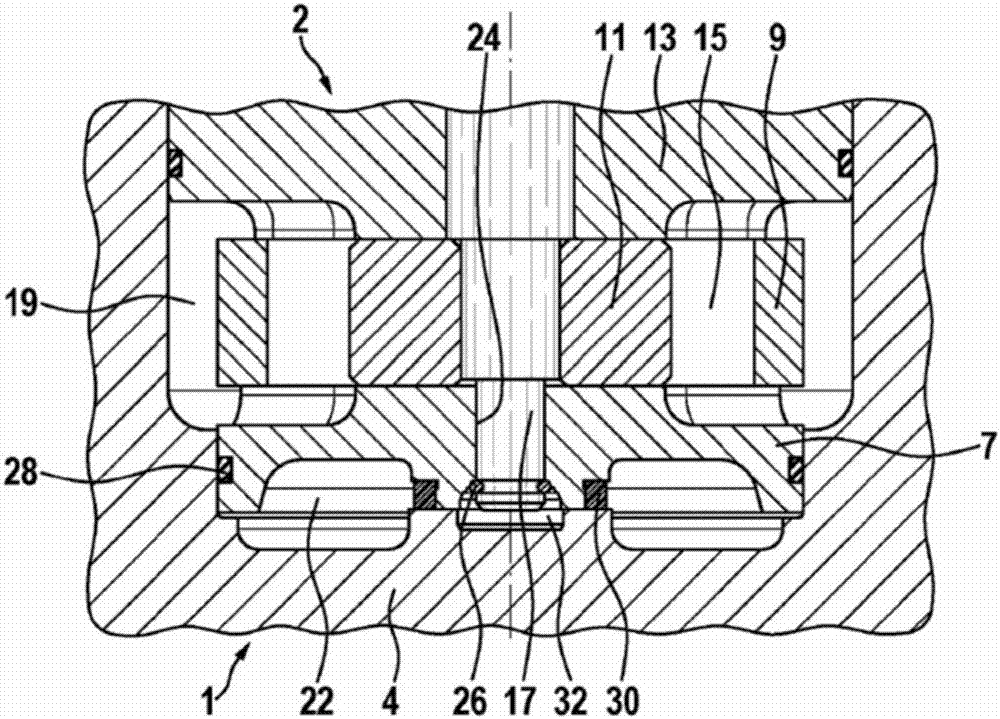
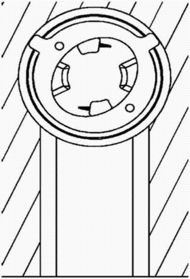
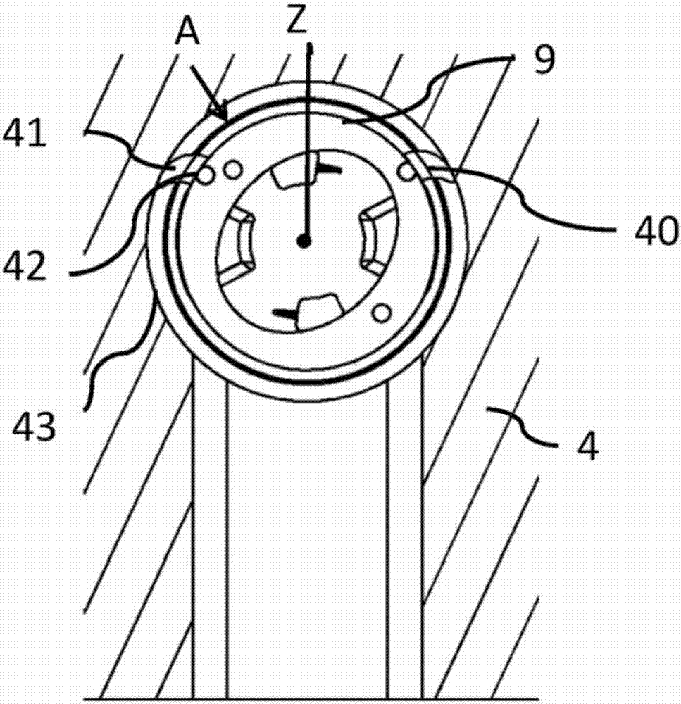
[0014] figure 1 A cross section of the pump 1 is shown. The pump 1 comprises a pump insert 2 which, for the sake of illustration of the pump 1 , is mounted in a separate gearbox 4 . In this example, the gearbox 4 contains a stepped blind hole in which the pump insert 2 is arranged. The pump insert 2 comprises a first pressure plate 7 , a contour ring 9 , a rotor 11 and a second pressure plate 13 . Radially displaceable blades 15 are arranged in slots of the rotor 11 , which run during rotation of the rotor 11 in such a way that their blade upper edges follow the contour of the contour ring 9 , wherein the contour ring 9 Also known as a cam ring. In a manner corresponding to the profile of the profile ring or cam ring 9 , here between two adjacent vanes 15 small chambers are formed, the size of which increases or decreases depending on the profile section, and between the increased or reduced dimensions During the reduction, the chamber sucks up oil and ejects it again.
...
PUM
 Abstract
Description
Claims
Application Information
 - R&D Engineer
- R&D Manager
- IP Professional
- Industry Leading Data Capabilities
- Powerful AI technology
- Patent DNA Extraction
Browse by: Latest US Patents, China's latest patents, Technical Efficacy Thesaurus, Application Domain, Technology Topic, Popular Technical Reports.
© 2024 PatSnap. All rights reserved.Legal|Privacy policy|Modern Slavery Act Transparency Statement|Sitemap|About US| Contact US: help@patsnap.com