Manual pressure relief type check valve

A one-way valve and pressure relief technology, applied in the field of manual pressure relief check valve, can solve the problem of abnormal pressure relief gas, backflow and other problems, reduce the requirements of materials and processes, facilitate two-way control, and increase the maximum value. Effect

Active Publication Date: 2017-08-01
GUANGZHOU XUTE ALUMINUM TECH CO LTD
View PDF6 Cites 1 Cited by
  • Summary
  • Abstract
  • Description
  • Claims
  • Application Information

AI Technical Summary

Problems solved by technology

[0006] The main purpose of the present invention is to provide a manually pressure-relief one-way valve to solve the defects of existing one-way valves that easily cause abnormal pressure relief or gas backflow

Method used


Image

  • Manual pressure relief type check valve
  • Manual pressure relief type check valve
  • Manual pressure relief type check valve

Examples


Embodiment 1

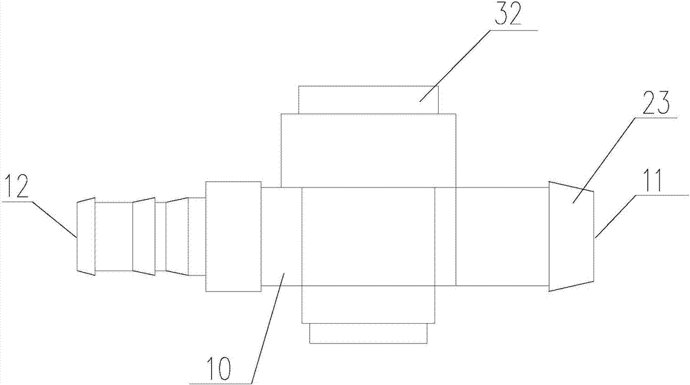
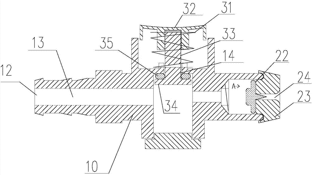
[0030] see Figure 1 to Figure 3 , the embodiment provides a manual pressure relief check valve, including a valve body 10, the valve body 10 has a first port 11 and a second port 12 that communicate with each other inside, and the first port 11 and the second port The channel between the ports 12 is a pressurized channel 13; a pressurization control device is installed at the first port 11.

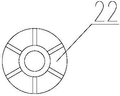
[0031] The pressure control device includes a closing element 22 and a sealing element 23; the sealing element 23 is fixed at the end face of the first port 11 (the sealing element 23 can be assembled on the first port 11 as an independent element, or can be assembled with the second port The end face of a port 11 is integrally formed), which has a pressurization through hole 24 that can communicate with the pressurization passage 13; the closure element 22 is elastically installed inside the pressurization passage 13, and the diameter of the closure element 22 is longer than the The di...

Embodiment 2

[0041] Such as Image 6 As shown, Embodiment 2 proposes a manually pressure-relief check valve, which differs from Embodiment 1 only in that the elastic element 31 is connected under the push rod to elastically support the push rod. The working principle of the second embodiment is similar to that of the first embodiment, and will not be repeated here.

Embodiment 3

[0043] Such as Figure 7 As shown, the manual pressure relief check valve proposed in Embodiment 3 differs from Embodiments 1 and 2 only in the design of the pressure relief control device. The pressure relief control device in Embodiment 3 includes a first screw cap 41 and the thimble 42 installed inside the first screw cap 41; the first screw cap 41 has an internal thread; the pressure relief port has an external thread that matches the internal thread of the first screw cap 41, so that the first screw cap 41 is screwed together On the pressure relief port; the pressure relief port has a connected middle passage 51 and a side hole 52, the middle passage 51 is connected with the pressurized passage; the thimble 42 is located in the middle passage 51, which is based on the first screw cap 41 and relative to the pressure relief The degree of screwing of the mouth opens or closes the side hole 52 accordingly.

[0044] In an optional solution, the pressure relief control device ...


PUM


Abstract

The invention relates to a manual pressure relief type check valve. A first end opening and a second end opening which communicate with each other are formed in a valve body. A channel between the first end opening and the second end opening is a pressurization channel. A pressurization control device is installed at the first end opening. The side face of the valve body is provided with a pressure relief opening communicating with the pressurization channel. A pressure relief control device is installed at the pressure relief opening. The pressurization control device comprises a closed element and a sealing element which is fixed to the end face of the first end opening and is provided with a pressurization through hole capable of communicating with the pressurization channel. The closed element is movably installed in the pressurization channel. The diameter length of the closed element is larger than the hole diameter of the pressurization through hole and is smaller than the diameter length of the position, where the closed element is located, of the pressurization channel. The manual pressure relief type check valve has higher reliability, the maximum value of air pressure in a container can be increased, the requirements for materials and a process are also lowered relatively, and cost can be reduced.

Description

technical field [0001] The invention belongs to the technical field of one-way valves, and in particular relates to a manually pressure-relieving one-way valve suitable for small pressurized equipment. Background technique [0002] As a mechanical component that can prevent the reverse movement of fluid, the check valve is widely used in mechanical equipment that needs to control the flow of fluid. For example, mercury sphygmomanometers and other inflatable devices with air bags use check valves. [0003] The structure of a general check valve includes a valve body and a valve core installed on the main channel (pressurized channel) inside the valve body. The valve core is a tube structure, the material is usually synthetic rubber, one end of the tube body has an opening, the other end is a blind end, and the side of the tube body has a linear cut that runs through the tube, and the cut is normally closed. [0004] The working principle of this one-way valve (take the one-w...

Claims


Application Information

Patent Timeline
Patent Type & Authority Applications(China)
IPC IPC(8): F16K15/02F16K17/02
CPCF16K1/00F16K1/32F16K1/36F16K15/02F16K15/025F16K15/18F16K17/02
Inventor 焦智
Owner GUANGZHOU XUTE ALUMINUM TECH CO LTD
Why Eureka
Try Eureka