Device and method of stopping motor stably

A motor and stable ground technology, which is applied in the control of electromechanical transmission, motor generator control, electronic commutation motor control, etc., can solve the problems of magnetic flux braking limit, motor temperature rise, large stator excitation loss, etc. To achieve the effect of preventing severe current changes and voltage changes

Active Publication Date: 2017-08-01
SHENZHEN INVT ELECTRIC
View PDF5 Cites 5 Cited by
  • Summary
  • Abstract
  • Description
  • Claims
  • Application Information

AI Technical Summary

Problems solved by technology

However, a larger stator excitation loss will also be generated, and this part of the lost energy will be converted into heat energy, resulting in an increase in the temperature of the motor
Therefore, for frequent braking occasions, the use of magnetic flux braking is limited

Method used


Image

  • Device and method of stopping motor stably
  • Device and method of stopping motor stably
  • Device and method of stopping motor stably

Examples


Embodiment 1

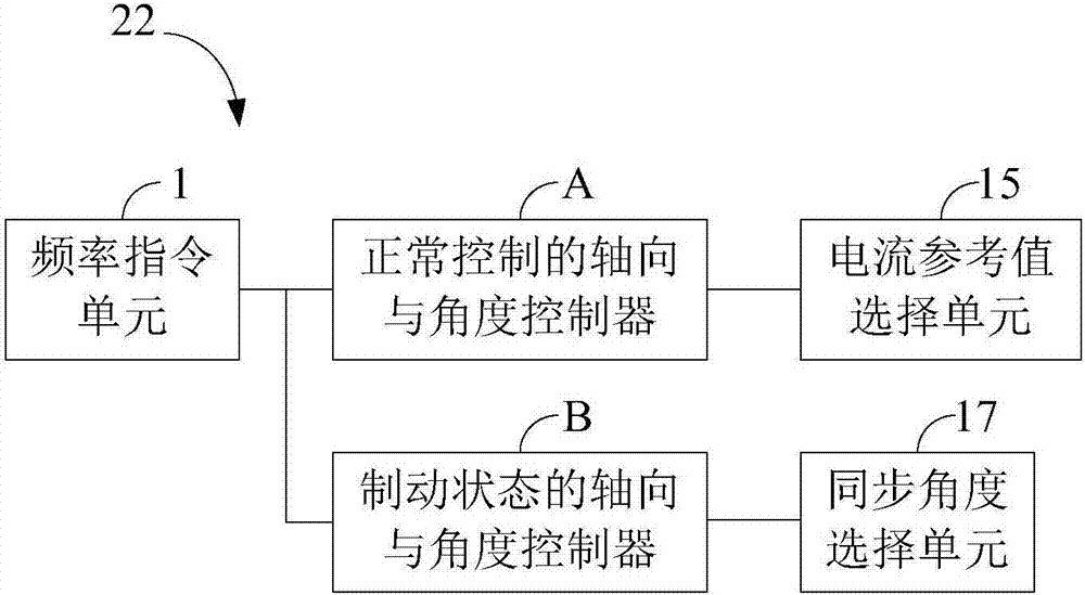
[0027] Such as figure 2 As shown, the inverter 22 in the motor stable stop device of this embodiment may include: a frequency command unit 1, an axial and angle controller A for normal control, an axial and angle controller B for braking status, and a current reference Value selection unit 15 and synchronization angle selection unit 17 .

[0028] The frequency instruction unit 1 is used for responding to a rotation speed instruction, and generating an operating frequency f_ref corresponding to the required rotation speed of the motor.

[0029] The normal control axis and angle controller A is used to generate the first q-axis current reference value iq_ref1 and the first d-axis current reference value id_ref1 when the motor is in the normal control mode, and estimate the real-time value of the rotor flux linkage of the motor 21 position to get the first synchronization angle Theta_fed. Specifically, the normal control axis and angle controller A may include a speed PI contr...

Embodiment 2

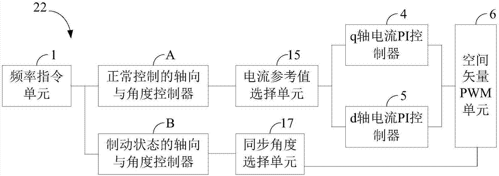
[0035] Such as image 3 As shown, the inverter 22 in the motor stabilizing stop device of this embodiment includes the frequency command unit 1 of Embodiment 1, the axial and angle controller A for normal control, and the axial and angle controller B for braking. In addition to the current reference value selection unit 15 and the synchronization angle selection unit 17 , it also includes a q-axis current PI controller 4 , a d-axis current PI controller 5 and a space vector pulse width modulation unit 6 . Among them, the q-axis current PI controller 4 is used to generate the q-axis voltage reference value Uq_ref according to the final q-axis current reference value; the d-axis current PI controller 5 is used to generate the d-axis voltage reference value according to the final d-axis current reference value Ud_ref; the space vector pulse width modulation unit 6 is used to generate the driving pulse sequence provided to the inverter unit 20 for driving the motor according to th...

Embodiment 3

[0037] Such as Figure 4 As shown, in addition to the corresponding components in Embodiment 2, the inverter 22 in the motor steady stop device of this embodiment also includes a rotor flux linkage angle observation and speed estimation unit 8, which is used for reference according to the two-phase stationary coordinate system The voltage and the current i_alfa and i_beta under the two-phase stationary coordinate system estimate the real-time position of the rotor flux linkage of the motor and the real-time frequency f_fed of the mechanical axis of the motor, wherein the real-time position of the rotor flux linkage of the motor includes the first synchronous angle, the mechanical axis The real-time frequency is fed back to form a closed-loop control of the speed with the operating frequency.


PUM


Abstract

The present invention relates to a device and method of stopping a motor stably. In the method, a first d-axis current reference value (id_ref1), a first q-axis current reference value (iq_ref1) and a first synchronization angle (Theta_fed) before the motor stop, are set as a second d-axis current reference value (id_ref2), a second q-axis current reference value (iq_ref2) and a second synchronization angle (Theta_ref) when the motor is stopped. Moreover, a normal control mode is switched to a stop brake mode, and the same proportional integral controllers (4,5) are used in the d-axis and the q-axis, so that the drastic current change and voltage change during the stop period of the motor is prevented, the motor can stop smoothly, and a pulsation phenomenon or a phenomenon that the motor reversely rotates and then stops, is not generated.

Description

technical field [0001] The application belongs to the technical field of electric motor control, and in particular relates to a device and a method for stably stopping the electric motor so that the motor shaft does not continue to rotate or swing back and forth when the electric motor stops. Background technique [0002] Current methods for stopping the motor include: inverter frequency reduction method, inverter output direct current method, and magnetic flux braking method. [0003] The inverter frequency reduction method means that when the inverter is used to drive the motor, the inverter reduces the output frequency according to a certain slope, so that the AC frequency applied to the motor gradually decreases. During this process, the generated torque is opposite to the rotation direction of the motor. From the input end of the motor, the motor does negative work and feeds back the mechanical energy consumed during the stop process, thereby realizing the shutdown of t...

Claims


Application Information

Patent Timeline
Patent Type & Authority Applications(China)
IPC IPC(8): H02P21/36H02P3/18
CPCH02P3/18H02P21/14
Inventor 刘军锋张东花徐铁柱
Owner SHENZHEN INVT ELECTRIC
Why Eureka
Try Eureka