Apparatus and method for stably stopping an electric motor
A motor, stop mode technology, applied in the control of electromechanical transmission, motor generator control, electronic commutation motor control, etc., can solve the problem of magnetic flux braking use limit, motor temperature rise, large stator excitation loss, etc. Achieve the effect of preventing severe current changes and voltage changes
- Summary
- Abstract
- Description
- Claims
- Application Information
AI Technical Summary
Problems solved by technology
Method used
Image
Examples
Embodiment 1
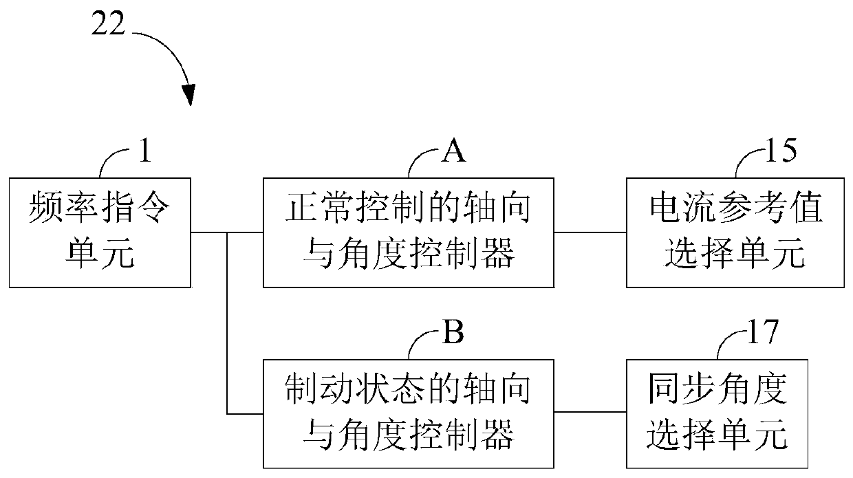
[0027] Such as figure 2 As shown, the inverter 22 in the motor stable stop device of this embodiment may include: a frequency command unit 1, an axial and angle controller A for normal control, an axial and angle controller B for braking status, and a current reference Value selection unit 15 and synchronization angle selection unit 17 .
[0028] The frequency instruction unit 1 is used for responding to a rotation speed instruction, and generating an operating frequency f_ref corresponding to the required rotation speed of the motor.
[0029] The normal control axis and angle controller A is used to generate the first q-axis current reference value iq_ref1 and the first d-axis current reference value id_ref1 when the motor is in the normal control mode, and estimate the real-time value of the rotor flux linkage of the motor 21 position to get the first synchronization angle Theta_fed. Specifically, the normal control axis and angle controller A may include a speed PI contr...
Embodiment 2
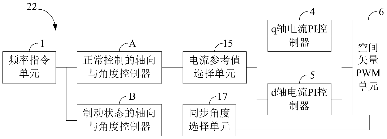
[0035] Such as image 3 As shown, the inverter 22 in the motor stabilizing stop device of this embodiment includes the frequency command unit 1 of Embodiment 1, the axial and angle controller A for normal control, and the axial and angle controller B for braking. In addition to the current reference value selection unit 15 and the synchronization angle selection unit 17 , it also includes a q-axis current PI controller 4 , a d-axis current PI controller 5 and a space vector pulse width modulation unit 6 . Among them, the q-axis current PI controller 4 is used to generate the q-axis voltage reference value Uq_ref according to the final q-axis current reference value; the d-axis current PI controller 5 is used to generate the d-axis voltage reference value according to the final d-axis current reference value Ud_ref; the space vector pulse width modulation unit 6 is used to generate the driving pulse sequence provided to the inverter unit 20 for driving the motor according to th...
Embodiment 3
[0037] Such as Figure 4 As shown, in addition to the corresponding components in Embodiment 2, the inverter 22 in the motor steady stop device of this embodiment also includes a rotor flux linkage angle observation and speed estimation unit 8, which is used for reference according to the two-phase stationary coordinate system The voltage and the current i_alfa and i_beta under the two-phase stationary coordinate system estimate the real-time position of the rotor flux linkage of the motor and the real-time frequency f_fed of the mechanical axis of the motor, wherein the real-time position of the rotor flux linkage of the motor includes the first synchronous angle, the mechanical axis The real-time frequency is fed back to form a closed-loop control of the speed with the operating frequency.
PUM
 Abstract
Description
Claims
Application Information
 - R&D
- Intellectual Property
- Life Sciences
- Materials
- Tech Scout
- Unparalleled Data Quality
- Higher Quality Content
- 60% Fewer Hallucinations
Browse by: Latest US Patents, China's latest patents, Technical Efficacy Thesaurus, Application Domain, Technology Topic, Popular Technical Reports.
© 2025 PatSnap. All rights reserved.Legal|Privacy policy|Modern Slavery Act Transparency Statement|Sitemap|About US| Contact US: help@patsnap.com


