
Connecting rod clamping device

A connecting rod clamp and connecting rod technology, which is applied in the direction of chucks, manipulators, program control manipulators, etc., can solve problems such as product jaw damage, and achieve the effect of simple assembly

Inactive Publication Date: 2017-08-04
BOZHON PRECISION IND TECH CO LTD
View PDF10 Cites 2 Cited by
  • Summary
  • Abstract
  • Description
  • Claims
  • Application Information

AI Technical Summary

Problems solved by technology

[0004] However, the above-mentioned clamping device that converts the linear motion of the linear motion element into the gripping action of the jaws has the following technical problems: when the jaws are in contact with the product, the jaws and the product are in line contact, and the jaws are in the process of clamping the product. There is relative sliding between the center and the product, so the product is vulnerable to damage from the jaws

Method used


Image

  • Connecting rod clamping device
  • Connecting rod clamping device
  • Connecting rod clamping device

Examples


Embodiment Construction

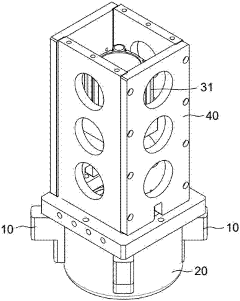
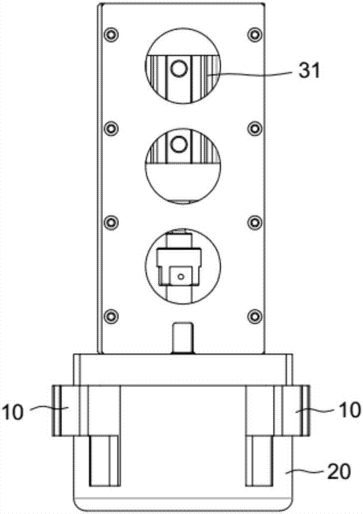
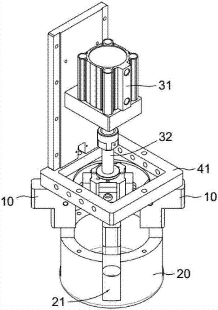
[0030] refer to figure 1 , figure 2 , a connecting rod clamping device, including a linear power assembly installed on the device frame, a connecting rod 11 connected to the linear power assembly, a jaw 10 connected to the connecting rod, fixed on the device frame The product positioning body 20.

[0031] refer to image 3 , Figure 4 , the product positioning body 20 is cylindrical, the top of the product positioning body 20 is open, the bottom of the product positioning body is provided with a bottom plate, and four chutes 21 are opened on the side wall of the product positioning body, and the four chutes are evenly distributed along the circumferential direction of the product positioning body . Described chute 21 is to offer the vertical bar-shaped notch on the side wall of product positioning body, and this vertical bar-shaped notch is opened to the bottom surface of the cavity in product positioning body 20, namely the bottom surface of chute and the top surface of ...


PUM


Abstract

A connecting rod clamping device comprises a linear power assembly mounted on a device rack, a connecting rod connected with the linear power assembly and a clamping claw connected with the connecting rod; and the clamping claw is arranged in a sliding groove in the side wall of a product positioning body in a sliding fit mode, and the product positioning body is fixed to the device rack. According to the scheme, reciprocating longitudinal linear movement of the linear power assembly is converted into unfolding and folding actions of the clamping claw, so that contacting between the clamping claw and a clamped product is surface contacting, no relative sliding exists between the clamping claw and the clamped product, and the product is effectively prevented from being damaged by the clamping claw.

Description

technical field [0001] The invention relates to a clamping device for products. Background technique [0002] In the device for clamping parts, elastic parts (such as springs) are generally used for the reset of the jaws. Specifically, when the jaws clamp the parts, the elastic parts accumulate elastic potential energy, and when the jaws release the parts, the elastic parts release the elastic potential energy to make the clip Claw reset. The elastic part is a wearing part, the service life is not long, and it is easy to reduce the action precision of the gripper jaw. An internal clamping mechanism for table legs as described in the invention patent application document with application number CN201520991038.X. [0003] In the prior art, in addition to the above-mentioned device using elastic parts to reset the jaws, there is also a clamping device that uses a linkage mechanism to convert the linear motion of the linear motion element into the clamping action of the jaws. ...

Claims


Application Information

Patent Timeline
IPC IPC(8): B25J15/08B25J9/08B25J9/14
CPCB25J15/08B25J9/08B25J9/14
Inventor 杨俊领盛绍雄
Owner BOZHON PRECISION IND TECH CO LTD
Learn More