Plasma detector and laser beam machine with plasma detector

Active Publication Date: 2005-08-18
YAMAZAKI MAZAK KK
View PDF7 Cites 22 Cited by
  • Summary
  • Abstract
  • Description
  • Claims
  • Application Information

AI Technical Summary

Benefits of technology

[0033] According to this aspect of the invention, spatter can be detected on the basis of the voltage slope, so that the process of computing the voltage slope to be implemented a

Problems solved by technology

If provided, the plasma detector has a complex structure, inconveniently.
But, it is difficult to easily detect plasma harmful to machining only by watching the trace voltage since the trace voltage at the time when generati

Method used


Image

  • Plasma detector and laser beam machine with plasma detector
  • Plasma detector and laser beam machine with plasma detector
  • Plasma detector and laser beam machine with plasma detector

Examples


Embodiment Construction

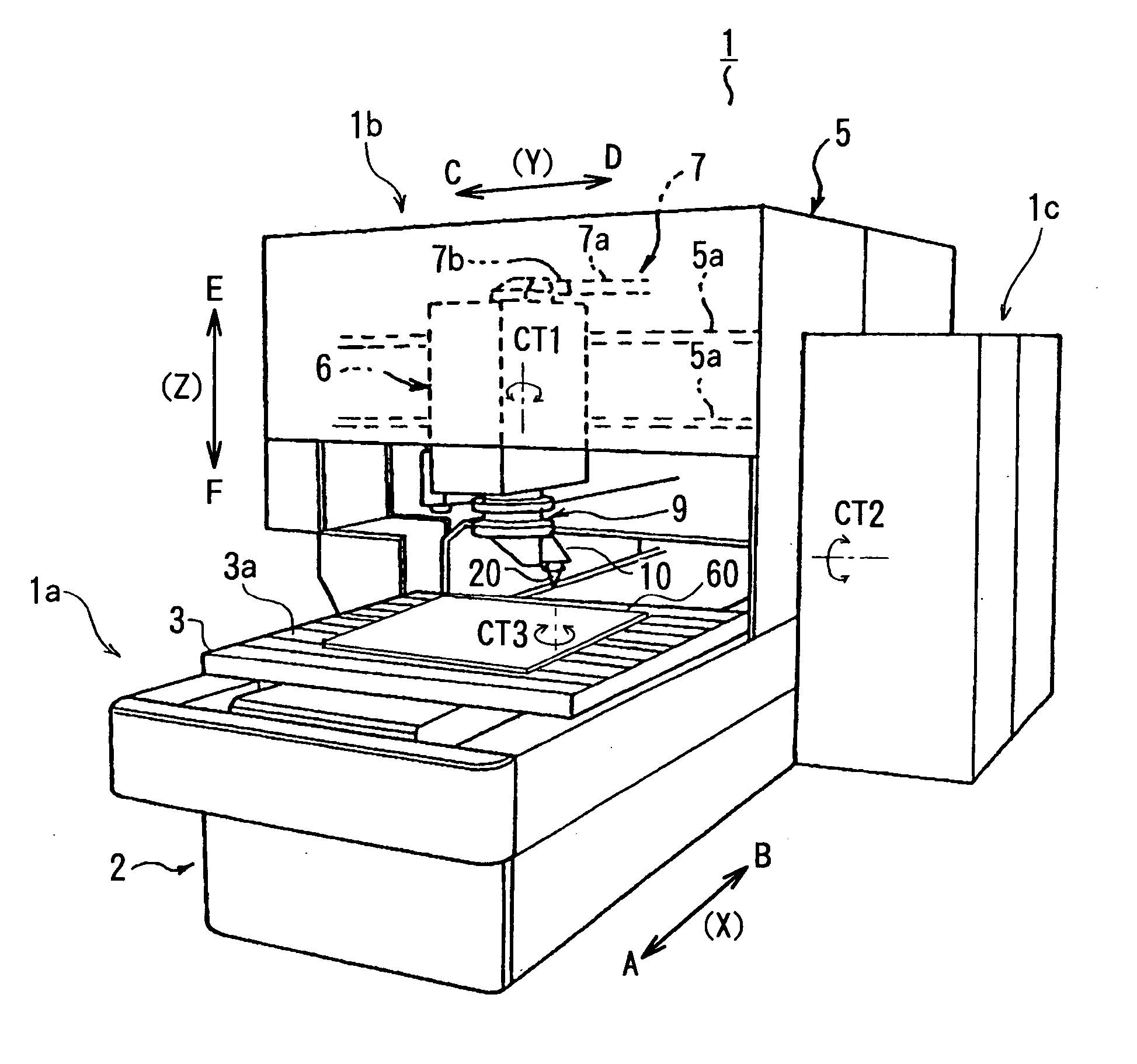
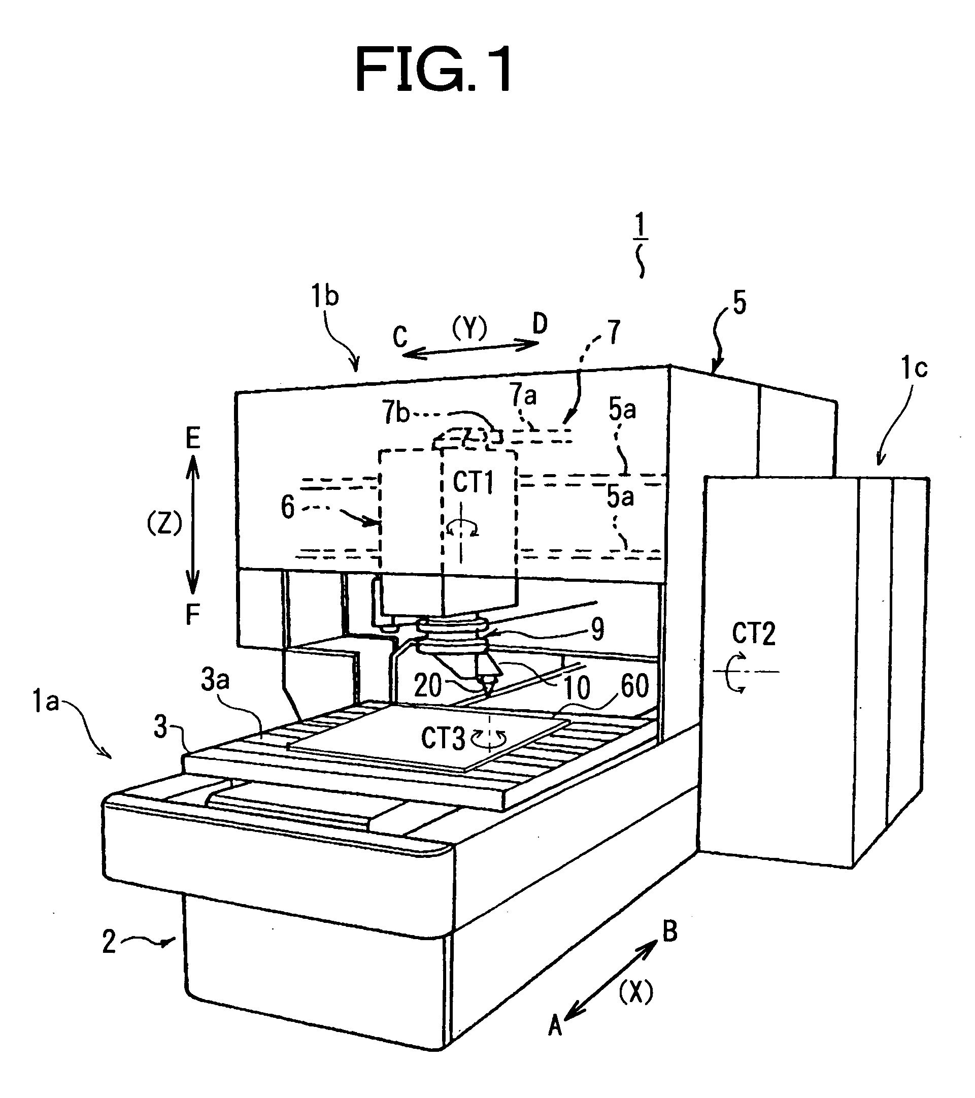
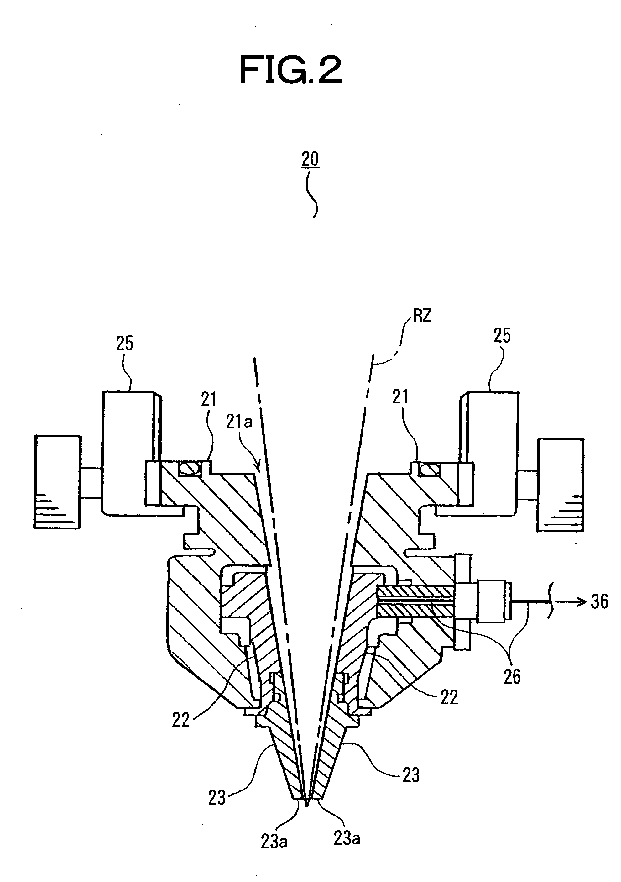
[0040]FIG. 1 is a perspective view showing the whole laser beam machine to which the invention is applied, FIG. 2 is a schematic side view (sectional view in a part) showing a torch, FIG. 3 is a block diagram showing a control unit, FIG. 4 is an explanation view of trace control wherein (a) shows capacitance when no plasma generating and (b) shows capacitance when large volume of plasma generating, FIG. 5 is a time chart at the time when generating spatter wherein (a) is trace voltage, (b) is voltage slope and (c) is control signal, and FIG. 6 is a time chart at the time when large volume of plasma generating wherein (a) is trace voltage, (b) is voltage slope, (c) is a control signal and (d) is an integrated signal.

[0041]FIG. 1 shows a laser beam machine 1 which is an embodiment of the present invention. The laser beam machine 1 to which the invention is applied is a CNC unit for machining (NC cutting machine), for instance. The laser beam machine 1 has a workpiece stationing unit ...


PUM

PropertyMeasurementUnit
Speedaaaaaaaaaa
Electric potential / voltageaaaaaaaaaa

Abstract

Voltage fluctuating time integrating means integrates voltage fluctuating time when voltage of a sensor electrode fluctuates as a voltage fluctuation integrated time, and voltage fluctuation occurrence rate computing means computes a rate of occurrence of voltage fluctuation for time on the basis of the voltage fluctuation integrated time integrated. By doing so, quantity of generated plasma can be taken as the rate of occurrence of voltage fluctuation, and plasma detection judging means can easily detect large volume of generated plasma on the basis of the computed voltage fluctuation occurrence rate. Then, it is not necessary to provide a circuit for measuring electric resistance between the sensor electrode and a workpiece as a conventional way, thereby avoiding complexly structured plasma detector.

Description

BACKGROUND OF THE INVENTION [0001] The invention relates to a plasma detector and a laser beam machine with a plasma detector. Particularly, the invention relates to a plasma detector and a laser beam machine with a plasma detector for easily detecting plasma harmful to machining, having no complex structure. [0002] Such kind of known conventional plasma detector measures electric resistance between a sensor electrode provided at a top end of a torch and a workpiece, and detects plasma generating from the workpiece on the basis of the measured electric resistance. When generating plasma, the voltage of a sensor electrode (“the trace voltage” hereinafter) fluctuates irrespective of a gap length between the torch and the workpiece, so that trace control does not nomally function. And, the portion between the sensor electrode and the workpiece is filled with charged particles comprising the generated plasma. For this reason, the above-mentioned electric resistance shows a predetermined...

Claims


Application Information

Patent Timeline
IPC IPC(8): B23K26/03B23K26/00
CPCB23K26/38B23K26/03
Inventor YAMAZAKI, TSUNEHIKOMIYAGAWA, NAOOMI
Owner YAMAZAKI MAZAK KK
Why Eureka
Try Eureka