Metal carrier and manufacturing method of metal carrier

A technology of metal carrier and manufacturing method, which is applied in the direction of catalyst carrier, catalyst carrier, chemical instrument and method, etc., can solve the problems of metal carrier shedding, cost increase, performance decline, etc., and achieve the effect of preventing deformation and preventing the decline of purification performance

Inactive Publication Date: 2007-08-01
CALSONIC KANSEI CORP
View PDF1 Cites 23 Cited by
  • Summary
  • Abstract
  • Description
  • Claims
  • Application Information

AI Technical Summary

Problems solved by technology

[0007] As mentioned above, in the metal carrier 101 proposed in Japanese Patent No. 2779516, when the metal carrier 101 is pressed into the cylindrical housing 102, the shape of the small chamber is locally deformed due to the step H at the end portion being rolled up. Since the deformation propagates toward the center, the shape of the metal carrier 101 is different from the designed shape, which leads to a problem of performance degradation.
[0008] In addition, as in the ceramic carrier 111 with a honeycomb structure proposed in Japanese Patent Application Laid-Open No. 2004-36398, when a buffer member 113 with a constant thickness is used to hold a metal carrier, the buffer member 113 cannot absorb the step H at the end portion of the roll. Carrier retention is unstable, so there are problems such as metal carrier falling off
In addition, since the buffer member 113 is required as an additional component, the cost increases

Method used


Image

  • Metal carrier and manufacturing method of metal carrier
  • Metal carrier and manufacturing method of metal carrier
  • Metal carrier and manufacturing method of metal carrier

Examples


no. 1 Embodiment approach

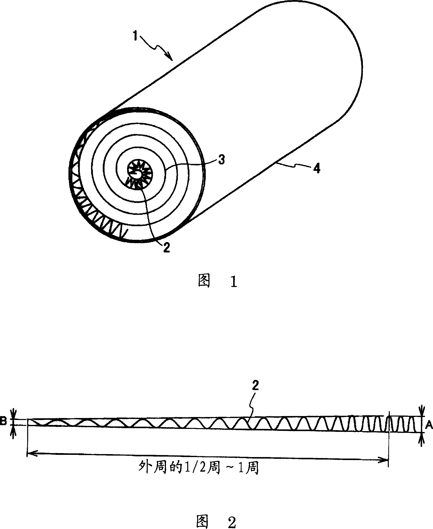
[0040] Next, a first embodiment of the present invention will be described with reference to the drawings. FIG. 1 is a perspective view showing the structure of a metal carrier according to this embodiment.

[0041]As shown in FIG. 1 , the metal carrier 1 of the present embodiment is formed by laminating metal belt-shaped corrugated foils 2 and flat foils 3 , rolling them into a spiral shape, and then winding them on the outer periphery. The brazing foil is pressed into the metal casing 4, and the corrugated foil 2 and the flat foil 3 are diffusely bonded by heating in a vacuum state, and these foils and the casing 4 are brazed to form a metal casing. Carrier 1.

[0042] Here, the shape of the corrugated foil 2 at the end of the roll of the metal carrier 1 will be described with reference to FIG. 2 . As shown in FIG. 2, by gradually expanding the wave pitch of the corrugated foil 2 with wave height A, the wave height is reduced to B. The wave height B is 1 / 3 to 1 / 4 of the w...

no. 2 Embodiment approach

[0056] Next, a method of manufacturing a metal carrier according to a second embodiment will be described with reference to the drawings. FIG. 7 is a diagram showing the configuration of a processing device for gradually reducing the wave height of the corrugated foil 2 . As shown in FIG. 7 , the processing device 71 has a die 73 formed with grooves 72 a to 72 g for fixing the wave tops of the corrugated foil 2 , and punches 74 a to 74 g for inserting the wave troughs of the corrugated foil 2 . However, as a mechanism for lowering the punches 74a to 74g, a general method such as a method using a cam mechanism or a method using an actuator can be used.

[0057] In the processing device 71 constituted in this way, FIG. 7 shows the state before processing, and grooves 72a to 72g are prepared on the die 73 at the positions of the processed state according to the number of crests of the corrugated foil 2 .

[0058] On the other hand, the punches 74a to 74g have a shape correspondi...

no. 3 Embodiment approach

[0064] Next, a method of manufacturing a metal carrier according to a third embodiment will be described with reference to the drawings. 11 to 13 are diagrams showing the structure of a processing device for gradually reducing the wave height of the corrugated foil 2. FIG. 11 is a front view, FIG. 12 is a plan view from above, and FIG. Side view of the corrugated foil in the upper state.

[0065] As shown in FIGS. 11 and 12 , the processing device 81 has a die 82 formed to have the shape of the corrugated foil 2 when it is completed, an elevator 83 for placing the corrugated foil 2 , and a pin 84 inserted into the trough of the corrugated foil 2 . , a block member 85 holding the pin 84 , a holding bolt 86 connecting the block members 85 , a spring 87 biasing the pin 84 , and a punch 88 formed in the shape of the corrugated foil 2 at the time of completion.

[0066] In the processing apparatus 81 configured in this way, the corrugated foil 2 is placed on the lifter 83 provided...


PUM


Abstract

The invention provides a metal carrier, wherein, the wound final end of the metal carrier is provided with stairs and the metal carrier has no small-chamber shaped local deformation even being pressed into a shell. The metal carrier (1) is produced by superposing a metal flat sheet (3) and a metal corrugated sheet (2) on each other and winding them. The invention is characterized in that at the wound end when the corrugated sheet (2) and the flat sheet (3) are wound, the corrugation height of the corrugated sheet (2) is gradually lowered.

Description

technical field [0001] The present invention relates to a metal carrier for purifying exhaust gas exhausted from internal combustion engines of automobiles and the like, and a method for producing the same. Background technique [0002] In the past, as a purification device with a built-in metal carrier, for example, as shown in the cross-sectional view of FIG. housing 102 . In this purification device, a corrugated foil 101a and a flat foil 101b are diffusion bonded, and a case 102 and a metal carrier 101 are brazed, and a catalyst is applied to the metal carrier 101 in this state. Further, diffusers 104 are welded to both ends of the case 102 to serve as inlets and outlets for introducing / leading exhaust gas to the catalyst unit (refer to Japanese Patent No. 2779516). [0003] In addition, as shown in the front view of FIG. 17 and the enlarged view of the main part of FIG. 18, the metal carrier 101 of the honeycomb structure is formed by alternately stacking strip-shaped...

Claims


Application Information

Patent Timeline
Patent Type & Authority Applications(China)
IPC IPC(8): B01J32/00B01J35/04B31F1/28
CPCF01N3/2814Y10T29/49345F01N2330/04F01N2330/325
Inventor 益子清二
Owner CALSONIC KANSEI CORP
Why Eureka
Try Eureka