Ball screw device

a screw and ball technology, applied in the direction of gearing, gearing elements, hoisting equipment, etc., can solve the problems of deflector mounting precision, increased cost of deflector, and degraded ball circulation performance,

Inactive Publication Date: 2004-10-14
JTEKT CORP
View PDF3 Cites 36 Cited by
  • Summary
  • Abstract
  • Description
  • Claims
  • Application Information

AI Technical Summary

Problems solved by technology

Such a ball screw device requires an externally mounted part, that is the deflector, which generates additional costs for the deflector, processing the through hole for mounting the deflector in the nut and mounting the deflector to the nut.
Besides, when the deflector is mounted to the through hole of the nut rather imprecisely, the ball circulation groove and thread groove cannot be precisely positioned, which results in a degraded circulation performance of the balls.
Thus, mounting the deflector requires precision, which is costly.

Method used


Image

  • Ball screw device
  • Ball screw device
  • Ball screw device

Examples


Embodiment Construction

[0020] Referring to FIGS. 1 through 7, a ball screw device according to a best mode for executing the present invention is hereinafter described in detail.

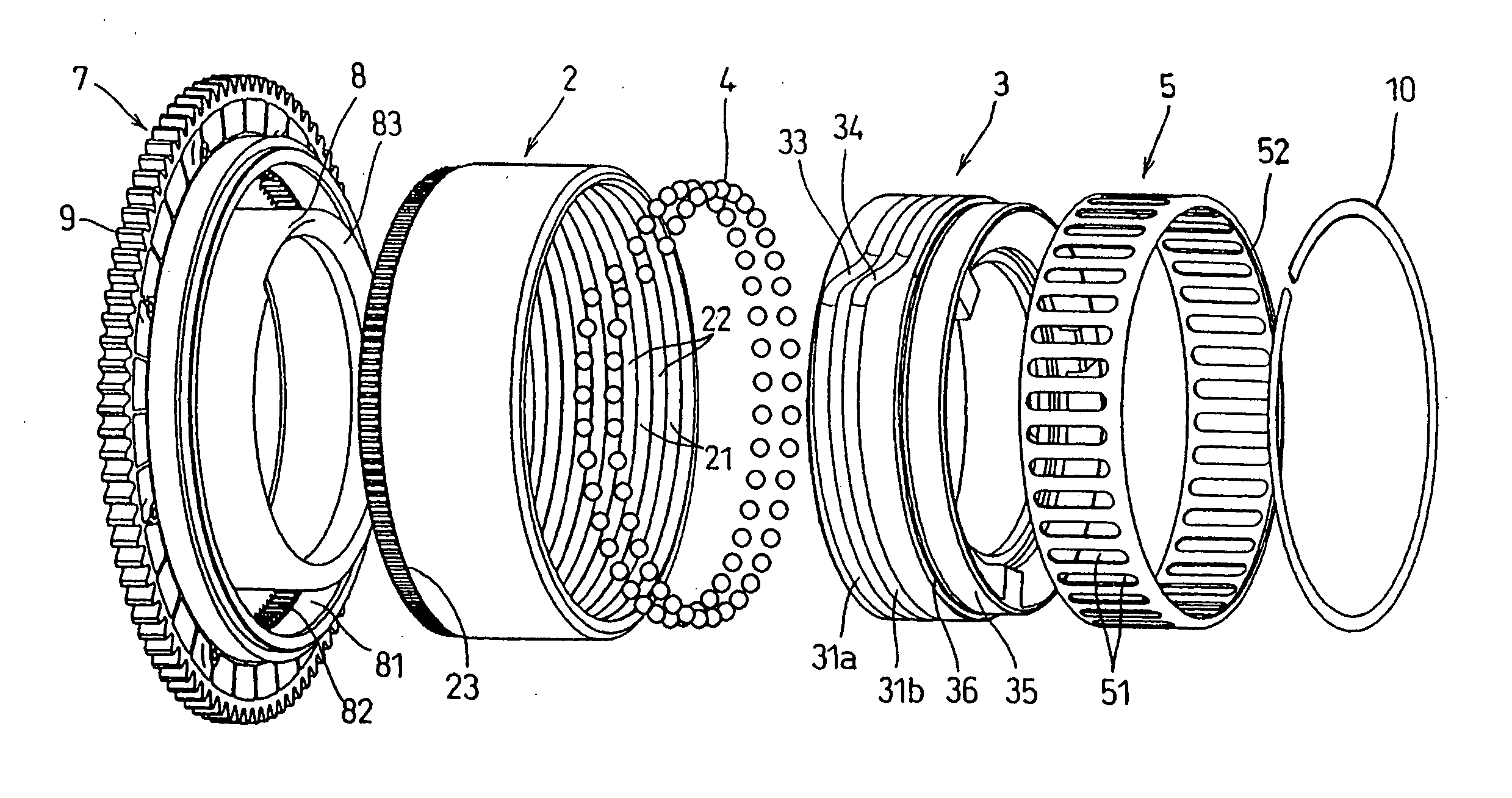
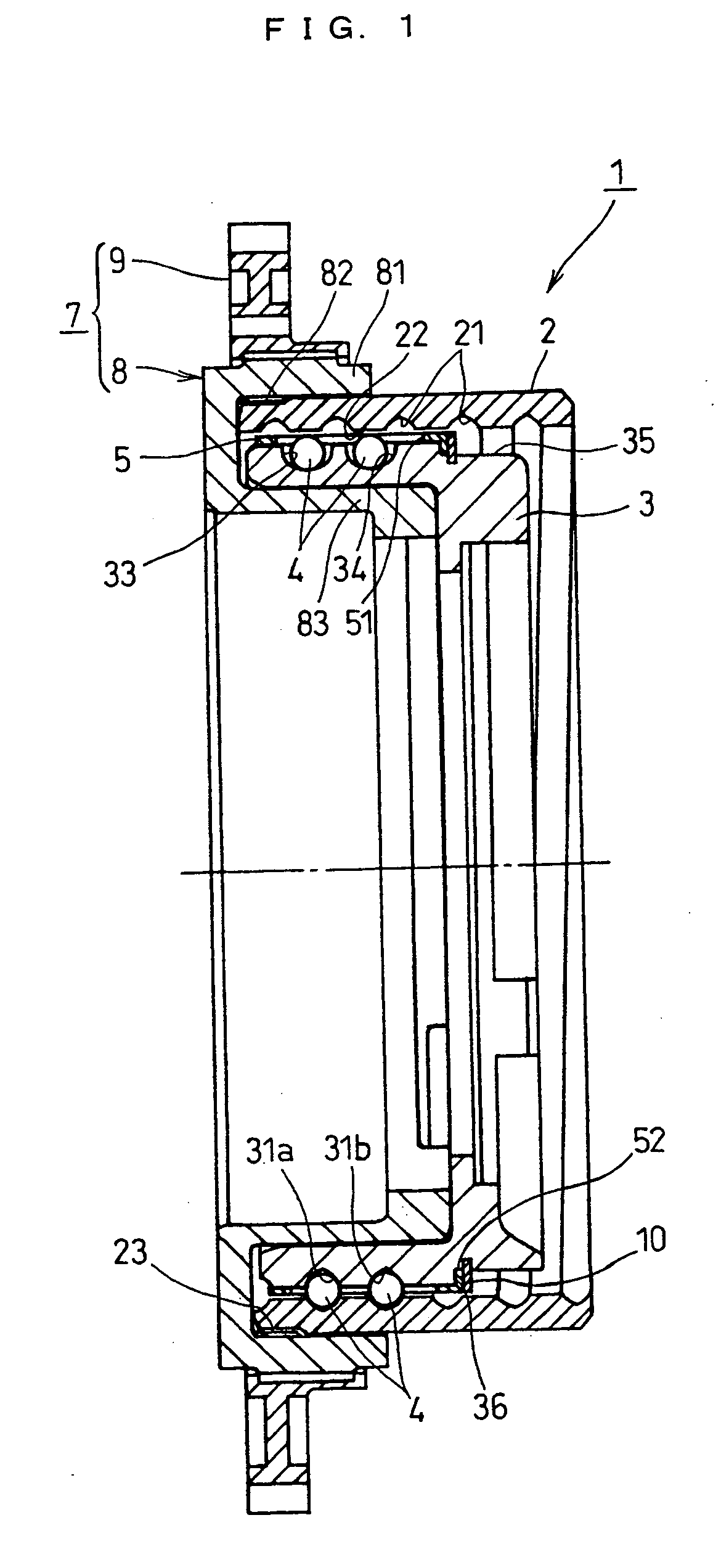
[0021] A ball screw device 1 comprises a nut 2, a screw shaft 3, a plurality of balls 4 and a retainer ring 5. The balls 4 are circulated between the opposing surfaces of the nut 2 and the screw shaft 3. In the nut 2 is formed a thread groove 21 continuous from one shaft end to another shaft end. In the axially intermediate region of the screw shaft 3 is formed a plurality of--two in this embodiment--thread grooves 31a and 31b, which are each of substantially one turn and independent from one another. The thread groove 21 of the nut 2 and the thread grooves 31a and 31b of the screw shaft 3 are set at an identical lead angle. The thread grooves 21, 31a and 31b are arranged to be of Gothic arc shape in section, but may be semicircular in section.

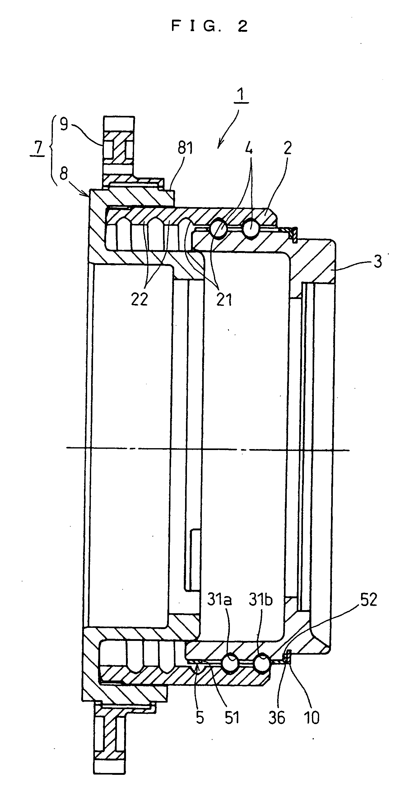
[0022] The nut 2 and the screw shaft 3 are in a maximally extended state, in which they ...


PUM


Abstract

A ball screw device comprises a nut having a thread groove in the inner peripheral surface thereof, a screw shaft having a thread groove in the outer peripheral surface thereof and a plurality of balls interposed between the respective thread grooves. In the screw shaft, the thread groove is of at least substantially one turn. In the screw shaft is provided a ball circulation groove for coupling the downstream and upstream sides of the thread groove so that the balls are returned to the upstream side from the downstream side so as to be thereby circulated.

Description

[0001] This invention relates to a ball screw device of ball circulation type.BACKGROUND TECHNIQUE[0002] A ball screw device comprises a screw shaft having a thread groove in the outer peripheral surface thereof and a nut having a thread groove in the inner peripheral surface thereof and externally mounted on the screw shaft. A plurality of balls are interposed between the respective thread grooves of the screw shaft and the nut. In such a ball screw device, the balls circulate between the respective thread grooves according to the rotational movement of the nut or the screw shaft, which causes a relative telescopic motion between the nut and the screw shaft. In this case, it is necessary, irrespective of the telescopic motion, to provide a structure to prevent the balls from slipping out of between the respective thread grooves. One of such structures is a ball circulation mechanism. The ball circulation mechanism couples both ends of a ball passageway shaped by the respective thre...

Claims


Application Information

Patent Timeline
Patent Type & Authority Applications(United States)
IPC IPC(8): F16H25/22F16H25/24
CPCF16H25/2204F16H25/2214F16H25/24Y10T74/19763Y10T74/19749Y10T74/19721Y10T74/19753F16H2025/2242F16H25/22
Inventor INOUE, MASAHIROUSUKI, ISAOMIKI, TATSUYUKI
Owner JTEKT CORP
Why Eureka
Try Eureka