Preheating control method, device and system of compressor

A preheating control and compressor technology, applied in the field of compressor control, can solve the problems of waste of preheating energy and long preheating time, and achieve the effect of reducing the preheating time and saving the preheating time

Active Publication Date: 2017-08-04
GREE ELECTRIC APPLIANCES INC
View PDF9 Cites 8 Cited by
  • Summary
  • Abstract
  • Description
  • Claims
  • Application Information

AI Technical Summary

Problems solved by technology

[0005] The embodiment of the present invention provides a compressor preheating control method, device and system to at least solve the technical problem of long preheating time of the screw chiller in the prior art, resulting in waste of preheating energy

Method used


Image

  • Preheating control method, device and system of compressor
  • Preheating control method, device and system of compressor
  • Preheating control method, device and system of compressor

Examples


Embodiment 1

[0018] According to an embodiment of the present invention, an embodiment of a preheating control method for a compressor is provided. It should be noted that the steps shown in the flow chart of the accompanying drawings can be executed in a computer system such as a set of computer-executable instructions, Also, although a logical order is shown in the flowcharts, in some cases the steps shown or described may be performed in an order different from that shown or described herein.

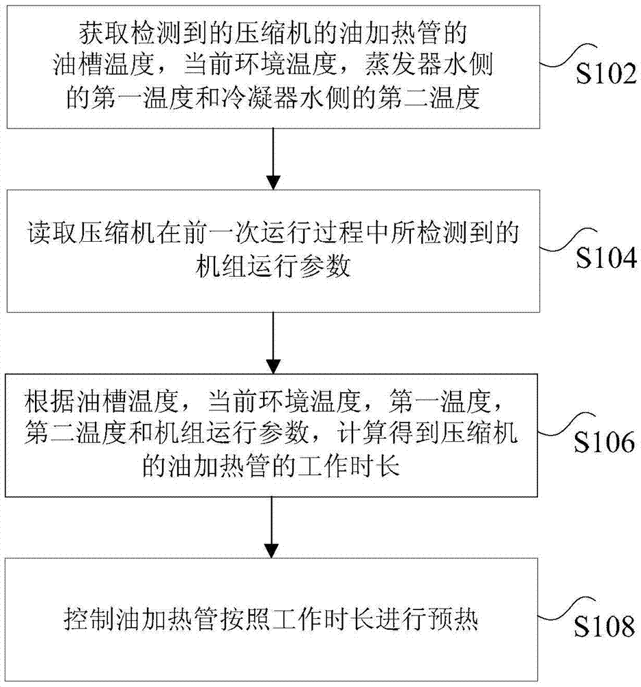
[0019] figure 1 is a flow chart of a compressor preheating control method according to an embodiment of the present invention, such as figure 1 As shown, the method includes the following steps:

[0020] Step S102, acquiring the detected temperature of the oil sump of the oil heating pipe of the compressor, the current ambient temperature, the first temperature of the water side of the evaporator, and the second temperature of the water side of the condenser.

[0021] Step S104, reading the ope...

Embodiment 2

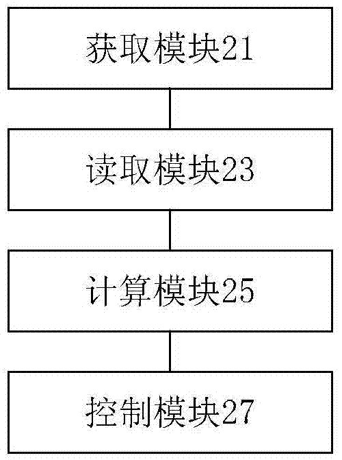
[0052] According to an embodiment of the present invention, an embodiment of a compressor preheating control device is provided, such as figure 2 As shown, the device includes: an acquisition module 21 , a reading module 23 , a calculation module 25 and a control module 27 .

[0053] Wherein, the acquiring module 21 is used to acquire the detected temperature of the oil tank of the oil heating pipe of the compressor, the current ambient temperature, the first temperature of the water side of the evaporator and the second temperature of the water side of the condenser.

[0054] The reading module 23 is used to read the operating parameters of the unit detected during the previous operation of the compressor.

[0055] Specifically, the above-mentioned unit operating parameters may be operating data of the unit itself.

[0056] The calculation module 25 is used to calculate the working time of the oil heating pipe of the compressor according to the temperature of the oil tank, ...

Embodiment 3

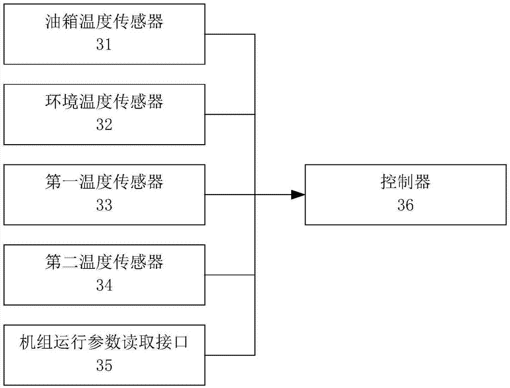
[0085] According to an embodiment of the present invention, an embodiment of a compressor preheating control system is provided, such as image 3 As shown, the system includes: a fuel tank temperature sensor 31 , an ambient temperature sensor 32 , a first temperature sensor 33 , a second temperature sensor 34 , a unit operating parameter reading interface 35 and a controller 36 .

[0086] Wherein, the oil tank temperature sensor 31 is used to detect the oil tank temperature of the oil heating pipe of the compressor.

[0087] The ambient temperature sensor 32 is used to detect the current ambient temperature.

[0088] The first temperature sensor 33 is used to detect the first temperature of the water side of the evaporator.

[0089] The second temperature sensor 34 is used to detect the second temperature of the water side of the condenser.

[0090] The unit operating parameter reading interface 35 is used to detect and obtain the unit operating parameters of the compressor ...


PUM


Abstract

The invention discloses a preheating control method, device and system of a compressor. The preheating control method comprises the following steps of: obtaining the detected oil groove temperature of an oil heating pipe of the compressor, current environment temperature, first temperature of the water side of an evaporator, and second temperature of the water side of a condenser; reading unit operation parameters of the compressor, which are detected during former operation; calculating the operating hours of the oil heating pipe of the compressor according to the oil groove temperature, the current environment temperature, the first temperature, the second temperature and the unit operation parameters; and controlling the oil heating pipe to perform preheating in accordance with the operating hours. The preheating control method disclosed by the invention solves the technical problem that in the prior art, energy sources for preheating are wasted because the preheating time of a screw-rod water chilling unit is long.

Description

technical field [0001] The invention relates to the field of compressor control, in particular to a compressor preheating control method, device and system. Background technique [0002] Refrigeration oil is an important lubricant for the operation of the screw refrigeration compressor, which plays the role of lubrication, gap sealing, cooling, taking away particulate impurities, and ensuring the reliable operation of the unit. However, when the screw refrigeration unit is shut down for a long time, a large amount of refrigerant will be dissolved in the refrigeration oil, which not only dilutes the refrigeration oil, reduces the viscosity of the refrigeration oil, and affects the lubrication and sealing effect of the refrigeration oil, but also when the compressor starts , the rise of oil temperature causes a large amount of refrigerant to precipitate rapidly, resulting in the compression of the compressor liquid, which seriously affects the reliability of the screw compress...

Claims


Application Information

Patent Timeline
Patent Type & Authority Applications(China)
IPC IPC(8): F25B49/02
CPCF25B49/022F25B2600/02
Inventor 张丙龙忠铿罗炽亮李莹陈耿松吴宏择
Owner GREE ELECTRIC APPLIANCES INC
Why Eureka
Try Eureka