An automatic feeding steel bar cutting machine

A steel bar cutting machine, automatic feeding technology, applied in cleaning methods and appliances, chemical instruments and methods, smoke and dust removal, etc., to achieve the effects of improving work efficiency, facilitating automatic discharge and storage, and achieving efficiency

Active Publication Date: 2018-10-19
信丰启旭农业机械制造有限公司
View PDF9 Cites 0 Cited by
  • Summary
  • Abstract
  • Description
  • Claims
  • Application Information

AI Technical Summary

Problems solved by technology

[0003] In the process of using steel bars, it is often necessary to cut the steel bars into the same length, but the existing cutting machines generally have a relatively simple structure, and when in use, they often need to be manually fed, and the cut steel bars need to be manually sorted and processed. collect

Method used


Image

  • An automatic feeding steel bar cutting machine
  • An automatic feeding steel bar cutting machine
  • An automatic feeding steel bar cutting machine

Examples


Embodiment Construction

[0017] The following will clearly and completely describe the technical solutions in the embodiments of the present invention with reference to the accompanying drawings in the embodiments of the present invention. Obviously, the described embodiments are only some, not all, embodiments of the present invention. Based on the embodiments of the present invention, all other embodiments obtained by persons of ordinary skill in the art without making creative efforts belong to the protection scope of the present invention.

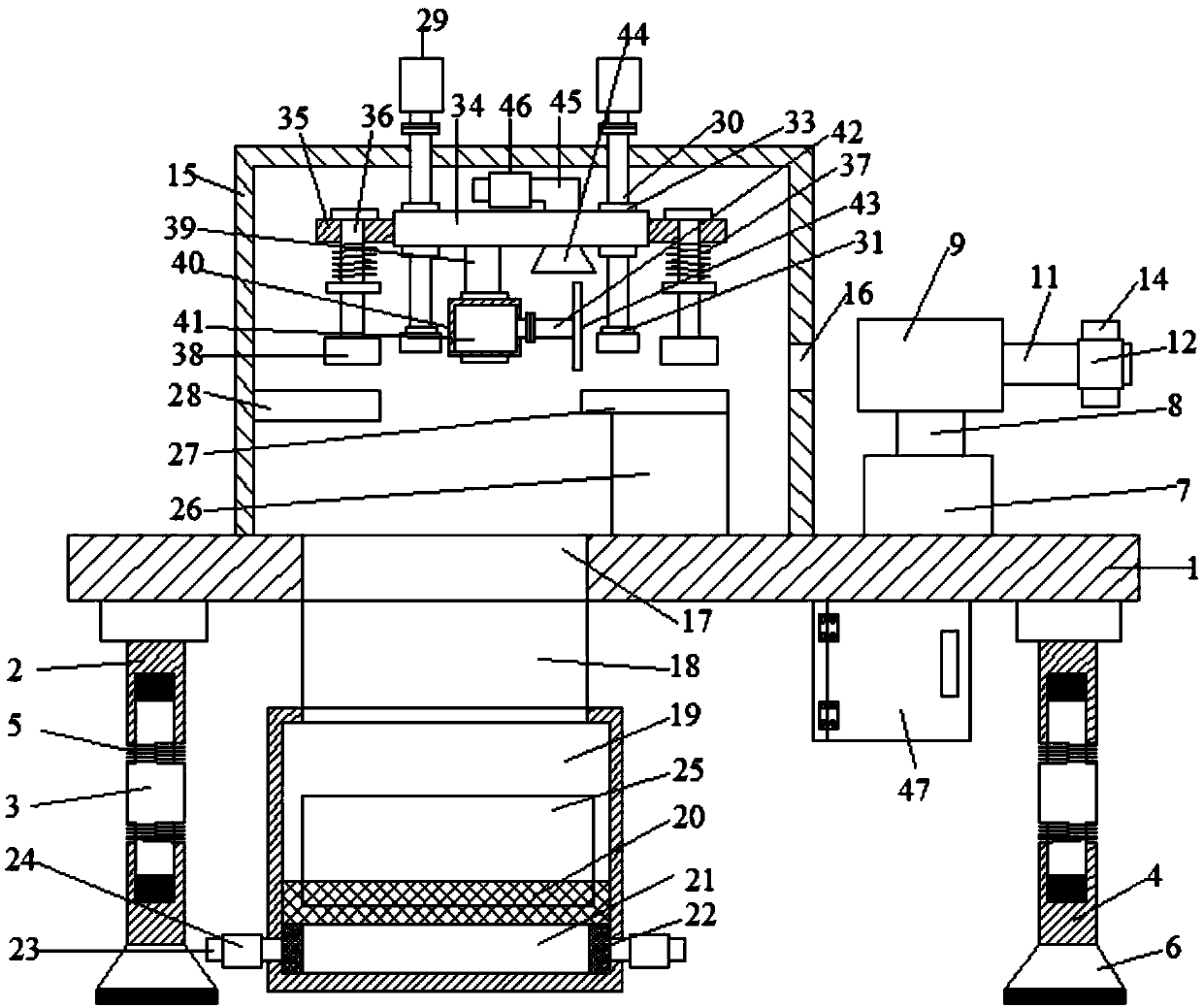
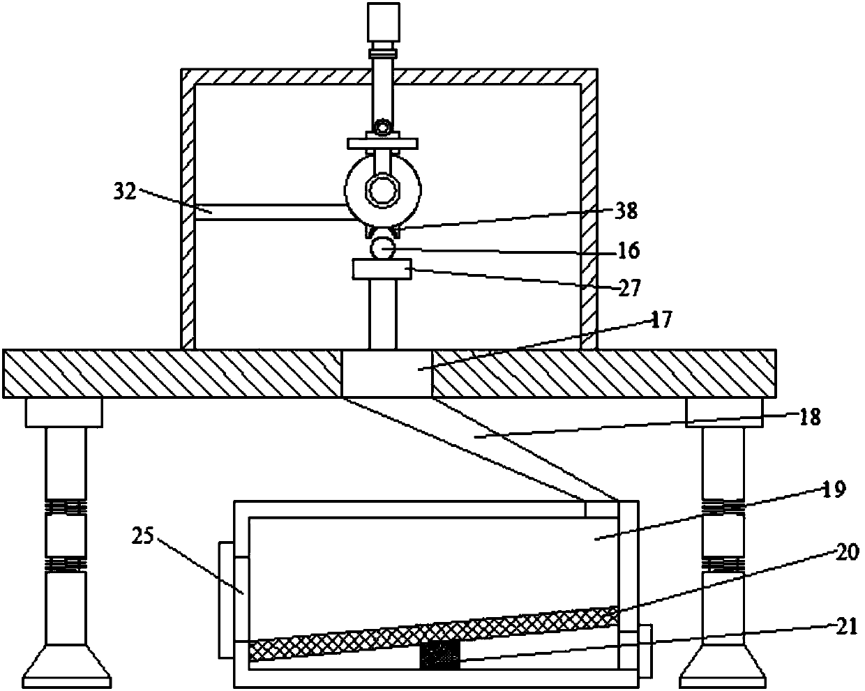
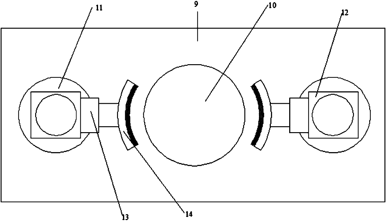
[0018] see Figure 1~3 , in an embodiment of the present invention, an automatic feeding steel bar cutting machine includes a support plate 1, a first support tube 2 is installed at the four corners of the lower side of the support plate 1, and a first connecting rod 3 is connected to the lower side of the first support tube 2, The middle part of the first connecting rod 3 is provided with a protrusion, the lower side of the first connecting rod 3 is provided ...


PUM


Abstract

The invention discloses a reinforcing steel bar cutting machine capable of feeding automatically. The reinforcing steel bar cutting machine capable of feeding automatically comprises a supporting plate; shock absorbing supporting devices are arranged at the four corners of the lower side of the supporting plate; an electric control box is arranged at the left end of the lower side of the supporting plate; an automatic clamping feeding device is arranged in the middle of the right end of the upper side of the supporting plate; a cutting box and an inclined discharging pipe of the cutting box are arranged on the left side of the automatic clamping feeding device; a material storage box is arranged on the lower side of the inclined discharging pipe; supporting legs are arranged at the right end of the upper side of an opening; a supporting table is arranged on the upper sides of the supporting legs; a baffle plate is arranged on the left side of the supporting table; a first motor is arranged on each of the front side and the rear side at each of the left end and the right end of the upper side of the cutting box; a screw rod is arranged on the lower side of each first motor; a fixed seat is arranged on the lower side of each screw rod; a connecting plate is arranged on each screw rod; a tightening fixing device is arranged on each of the left side and the right side of each connecting plate; a cutting device is arranged on the lower side of the supporting plate; an air blowing cover is arranged on the upper side of a cutting disc; a ventilating pipe is arranged on the upper side of the air blowing cover. According to the reinforcing steel bar cutting machine capable of feeding automatically, clamping, cutting and material discharging can be performed conveniently through the arrangement of an automatic feeding device, a lifting cutting device and a clamping device.

Description

technical field [0001] The invention relates to a steel bar processing equipment, in particular to an automatic feeding steel bar cutting machine. Background technique [0002] Reinforcement bar (also known as corrugated steel) is a strip made of steel, which is a kind of building material. For example, in reinforced concrete, the skeleton used to support the structure. [2] Including light round bars, ribbed bars, twisted bars. There are many types of steel bars, usually classified by chemical composition, production process, rolled shape, supply form, diameter, and use in structures. Steel bars mainly bear tensile stress in concrete. Due to the effect of the ribs, the deformed steel bar has a greater bonding capacity with the concrete, so it can better withstand the external force. Steel bars are widely used in various building structures, especially large, heavy, light thin-walled and high-rise building structures. [0003] In the process of using steel bars, it is of...

Claims


Application Information

Patent Timeline
Patent Type & Authority Patents(China)
IPC IPC(8): B21F11/00B21F23/00B08B15/04
CPCB08B15/04B21F11/00B21F23/00
Inventor 刘金定
Owner 信丰启旭农业机械制造有限公司
Why Eureka
Try Eureka