

Fan impeller and fan adopting same
A fan impeller and fan technology, applied to machines/engines, parts of pumping devices for elastic fluids, mechanical equipment, etc., can solve the problem of insufficient overall structure of the fan, unfavorable impeller working ability, limited improvement of fan efficiency, etc. problem, to achieve the effect of preventing oil fume from escaping, novel structure and good aerodynamic performance
Active Publication Date: 2017-08-08
NINGBO FOTILE KITCHEN WARE CO LTD
View PDF5 Cites 9 Cited by
- Summary
- Abstract
- Description
- Claims
- Application Information
AI Technical Summary
Problems solved by technology
At present, the traditional impellers for range hoods are generally formed by flat stamping and connected by fastening at both ends. Generally, the blades can only be made into circular arcs with uniform thickness. Since the impeller speed generally exceeds 800RPM, the actual fluid separation between the blades And the backflow is obvious, and because the impeller has a pre-rotation effect on the gas and the direction of the gas will gradually change during the 90° turning process of flowing into the impeller, the purely consistent inlet and outlet angles are not good for the actual working ability of the impeller
In order to improve the efficiency of the fan, although people have also made many improvements in the blade structure, these improvements are still limited to the binary flow technology, and the efficiency of the fan is relatively limited. The level of ordinary binary flow impeller technology seriously affects the fan. Performance, so it is still impossible to fundamentally overcome the defects of the above-mentioned binary impeller
In addition, if the impeller structure is not fundamentally changed, under the same wind pressure, the overall structure of the fan is not compact enough and the volume is relatively large
Method used
View moreImage
Smart ImageViewing Examples

Examples
Embodiment 2
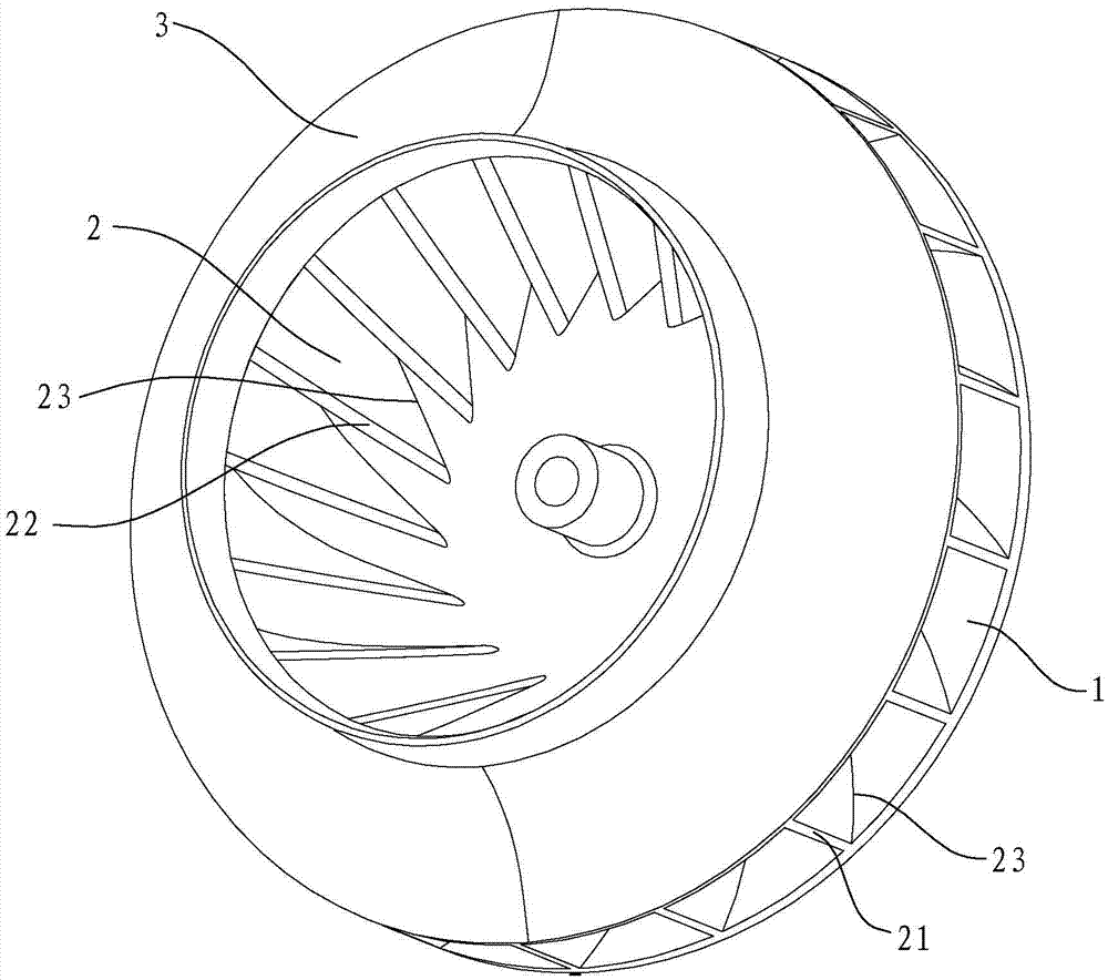
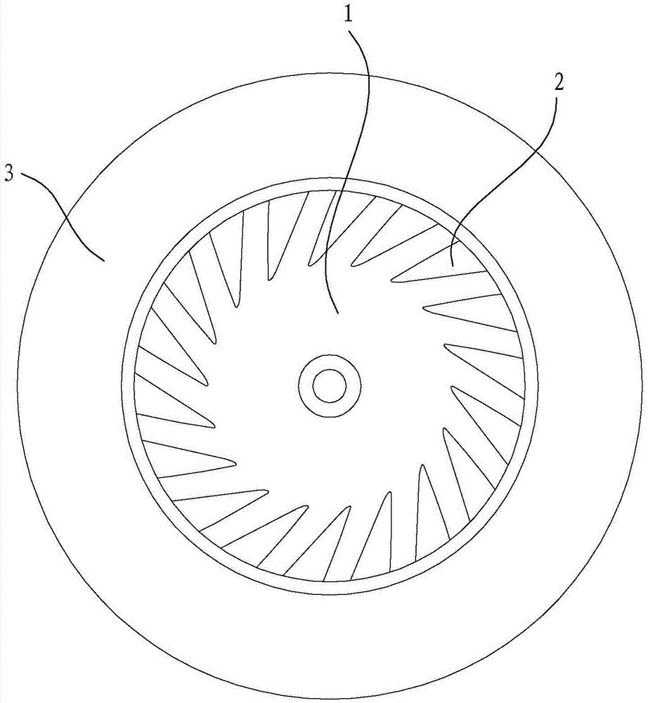
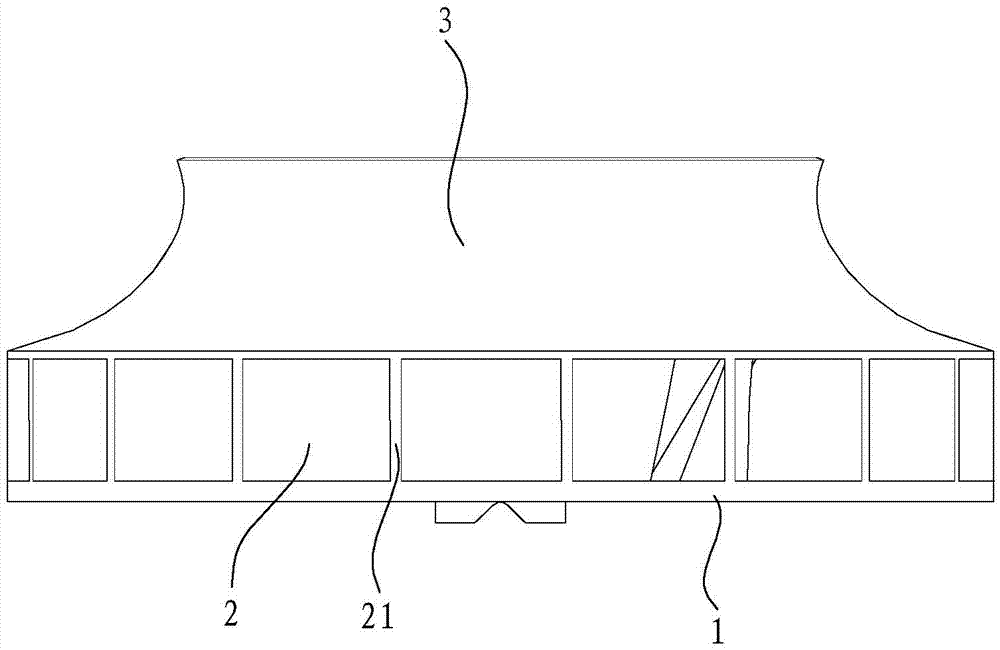
[0038] Such as Figure 13 As shown, the fan impeller of this embodiment is an open impeller, and the impeller includes a rear disc 1 and blades 2. Compared with the fan impeller in the first embodiment, the front cover is omitted for the impeller, and the rest of the structure is the same as that of the first embodiment. The structure in is the same and will not be described here.
Login to View More PUM
 Abstract
The invention discloses a fan impeller. The fan impeller comprises a rear impeller disc and blades, the bottoms of the blades are installed on the disc surface of the rear impeller disc, and the blades are sequentially arranged in the circumferential direction of the rear impeller disc; the outer side edge of each blade serves as an air outlet edge, wherein an included angle alpha formed between the projection of the outer side edge on the outer circumference face of the rear impeller disc and the normal line of the rear impeller disc is larger than or equal to minus 60 degrees and smaller than or equal to 60 degrees; the inner side edge of each blade serves as an air inlet edge, wherein an included angle beta formed between the projection of the inner side edge on the outer circumference face of the rear impeller disc and the normal line of the rear impeller disc is larger than or equal to 20 degrees and smaller than or equal to 70 degrees; an included angle theta formed between a connecting line between the bottom end of each outer side edge and the circle center of the rear impeller disc and a connecting line between the bottom end of each inner side edge and the circle center of the rear impeller disc is larger than or equal to 10 degrees and smaller than or equal to 65 degrees, and the vertical height h1 of the vertex point of each outer side edge relative to the rear impeller disc is smaller than the vertical height h2 of the vertex point of each inner side edge relative to the rear impeller disc. The invention further discloses a fan adopting the fan impeller. The fan impeller has the advantages of being novel in structure and good in pneumatic performance; the fan adopting the impeller has the advantages of being compact in structure, high in fan efficiency and air pressure and large in generated negative pressure gradient.
Description
technical field [0001] The invention relates to a fan, in particular to a fan impeller and a fan using the impeller. Background technique [0002] The fan is an important part of the range hood. The impeller of the fan plays the role of energy conversion. The performance of the impeller directly affects the performance of the range hood. At present, the traditional impellers for range hoods are generally formed by flat stamping and connected by fastening at both ends. Generally, the blades can only be made into circular arcs with uniform thickness. Since the impeller speed generally exceeds 800RPM, the actual fluid separation between the blades And the backflow is obvious, and because the impeller has a pre-rotation effect on the gas and the direction of the gas will gradually change during the 90° turning process of the gas flowing into the impeller, the purely consistent inlet and outlet angles are not good for the actual working ability of the impeller. In order to impro...
Claims
Login to View More Application Information
Patent Timeline
 Patent Type & AuthorityApplications(China)
IPC IPC(8): F04D29/28F04D29/30F04D25/08
CPCF04D25/08F04D29/283F04D29/30F04D29/281F04D29/4253F04D29/4226
Inventor梁雪斐刘逸周佳杰茅忠群诸永定刘戈
OwnerNINGBO FOTILE KITCHEN WARE CO LTD