Wire harness cutting-off device

A technology for cutting devices and wire harnesses, which is applied in the field of automotive wire harnesses and can solve problems such as the inability to realize wire harness cutting

Active Publication Date: 2017-08-11
WUHU QIAOYUN & YOUXING ELECTRICAL IND CO LTD
View PDF8 Cites 3 Cited by
  • Summary
  • Abstract
  • Description
  • Claims
  • Application Information

AI Technical Summary

Problems solved by technology

The cutting device includes: a support platform, the substrate holding member is placed in a state where the circular opening coincides with the inner end of the frame, the substrate holding member stretches an adhesive film on the circular ring-shaped frame, The brittle material substrate is attached to the adhesive film; a pair of stages can move freely in the horizontal plane in the opening, and are spaced apart from each other in the horizontal plane so that the planned cutting position coincides with the formation position of the mutual gap The britt

Method used


Image

  • Wire harness cutting-off device
  • Wire harness cutting-off device
  • Wire harness cutting-off device

Examples


Embodiment 1

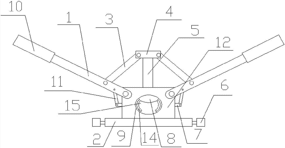
[0024] like figure 1 and figure 2 As shown, a wire harness cutting device includes a handle 1, a base 2 and a cutting table 12, the cutting table 12 is arranged on the base 2 of the cuboid structure, and the handle 1 has two and is symmetrically arranged on the cutting table On both sides of 12, the handle 1 is hinged with the shearing table 12, which can be used by two people to operate one handle 1 respectively. The top of the shearing table 12 is provided with a through hole, and a pressure column 5 is sleeved in the through hole. 5 can move up and down, the interior of the shearing table 12 is provided with a blade 8, the blade 8 is connected with the bottom of the pressure column 5, the top of the pressure column 5 is provided with a connecting table 4, and the connecting table 4 and the handle 1 are hinged There is a support rod 1 3, the two sides of the shearing table 12 are provided with notches, and a push rod 7 is sleeved in the groove; There is a support rod 11, ...

Embodiment 2

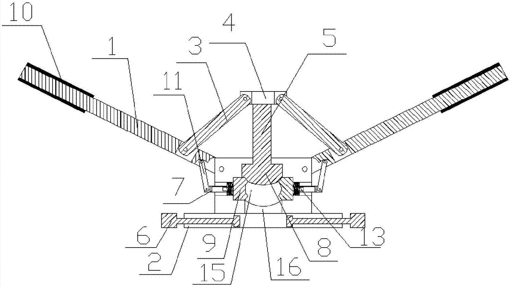
[0032] like image 3 and Figure 4 As shown, a wire harness cutting device includes a handle 1, a base 2 and a cutting table 12, the cutting table 12 is arranged on the base 2 of the cuboid structure, and the handle 1 has two and is symmetrically arranged on the cutting table On both sides of 12, the handle 1 is hinged with the shearing table 12, which can be used by two people to operate one handle 1 respectively. The top of the shearing table 12 is provided with a through hole, and a pressure column 5 is sleeved in the through hole. 5 can move up and down, the interior of the shearing table 12 is provided with a blade 8, the blade 8 is connected with the bottom of the pressure column 5, the top of the pressure column 5 is provided with a connecting table 4, and the connecting table 4 and the handle 1 are hinged There is a support rod 1 3, the two sides of the shearing table 12 are provided with notches, and a push rod 7 is sleeved in the groove; There is a support rod 11, ...

Embodiment 3

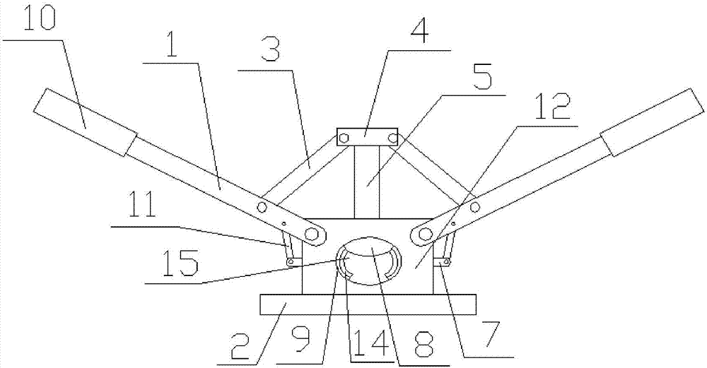
[0039] like Figure 5 and Image 6 As shown, a wire harness cutting device includes a handle 1, a base 2 and a cutting table 12, the cutting table 12 is arranged on the base 2 of the cuboid structure, and the handle 1 has two and is symmetrically arranged on the cutting table On both sides of 12, the handle 1 is hinged with the shearing table 12, which can be used by two people to operate one handle 1 respectively. The top of the shearing table 12 is provided with a through hole, and a pressure column 5 is sleeved in the through hole. 5 can move up and down, the interior of the shearing table 12 is provided with a blade 8, the blade 8 is connected with the bottom of the pressure column 5, the top of the pressure column 5 is provided with a connecting table 4, and the connecting table 4 and the handle 1 are hinged There is a support rod 1 3, the two sides of the shearing table 12 are provided with notches, and a push rod 7 is sleeved in the groove; There is a support rod 11, ...


PUM


Abstract

The invention discloses a wire harness cutting-off device and relates to the field of automobile wire harnesses. The wire harness cutting-off device comprises two handles, a base and a shearing platform; the shearing platform is arranged on the base with a cuboid structure; the two handles are symmetrically arranged at two sides of the shearing platform and are hinged with the shearing platform; a through hole is formed in the top of the shearing platform; a pressure column is sleeved by the through hole; a blade is arranged inside the shearing platform and is connected with the bottom of the pressure column; the top of the pressure column is provided with a connecting platform; a supporting rod I is hinged between the connecting platform and each handle; notches are formed in two sides of the shearing platform and are internally sleeved with push rods on which clamping pieces are arranged; a supporting rod II is hinged between each push rod and each handle; a shearing port is formed in the middle of the shearing platform; and both the blade and the clamping pieces are arranged in the shearing port. By using the cutting-off device, a wire harness can be fixed, so that the phenomenon that the efficiency is affected due to the slip off of the wire harness during cutting is avoided.

Description

technical field [0001] The invention relates to the field of automobile wiring harness, in particular to a wiring harness cutting device. [0002] Background technique: [0003] High-voltage wiring harnesses are often used in new energy vehicles. The high-voltage wiring harness is not only thick but also very hard. It is always very laborious to cut off the high-voltage wiring harness, and the wiring harness often slips away during cutting, which cannot be cut at one time. The cutting pliers are cut from the side, the pressure is not in the opposite direction to the resistance, and the cutting is more laborious. Therefore, it is necessary to design a cutting device that can fix the wire harness when cutting, and is more labor-saving. [0004] Chinese Patent Application No.: 201410011415.9 discloses a wire harness construction cutter, the jaw of which is divided into three parts from the pin shaft to the extension end of the jaw, and is sequentially constructed as a wire cutte...

Claims


Application Information

Patent Timeline
IPC IPC(8): B21F11/00
CPCB21F11/00
Inventor 周忠周顺刘陆明辛文彬晋秀兰
Owner WUHU QIAOYUN & YOUXING ELECTRICAL IND CO LTD
Why Eureka
Try Eureka