Linear array SAR (Synthetic Aperture Radar) three-dimensional imaging method based on threshold gradient tracking algorithm

A linear array and threshold technology, used in radio wave measurement systems, radio wave reflection/re-radiation, utilization of re-radiation, etc., can solve the problems of increase, cost increase, and high cost

Active Publication Date: 2017-08-11
UNIV OF ELECTRONICS SCI & TECH OF CHINA
View PDF7 Cites 22 Cited by
  • Summary
  • Abstract
  • Description
  • Claims
  • Application Information

AI Technical Summary

Problems solved by technology

Under the premise of the traditional imaging system and data processing method, in order to achieve high-resolution earth observation, the linear array 3D SAR imaging technology faces the following challenges: (1) The load conditions are limited: for the ka-band airborne platform, at a height of 3km, it is necessary to To realize observation with a resolution of 0.05m, the length of the linear array is required to be more than 300m, which is difficult to meet with the size of the existing airborne platform; (2) too many elements of the linear array: in order to suppress side lobes and grating lobes, it is usually necessary to use full sampling Line array antennas need to use thousands of array elements at least, and tens of thousands of array elements at most. The hardware system is complex and costly
(3) Insufficient imaging precision: At present, the back projection (BP) algorithm is mainly used for linear array 3D SAR data processing. The side lobe of the scattering target is covered, and the resolution of the cut track is often m

Method used


Image

  • Linear array SAR (Synthetic Aperture Radar) three-dimensional imaging method based on threshold gradient tracking algorithm
  • Linear array SAR (Synthetic Aperture Radar) three-dimensional imaging method based on threshold gradient tracking algorithm
  • Linear array SAR (Synthetic Aperture Radar) three-dimensional imaging method based on threshold gradient tracking algorithm

Examples


Embodiment Construction

[0086] The present invention mainly adopts the method of simulation experiment to verify, and all steps and conclusions are verified on MATLABR2008b. The specific implementation steps are as follows:

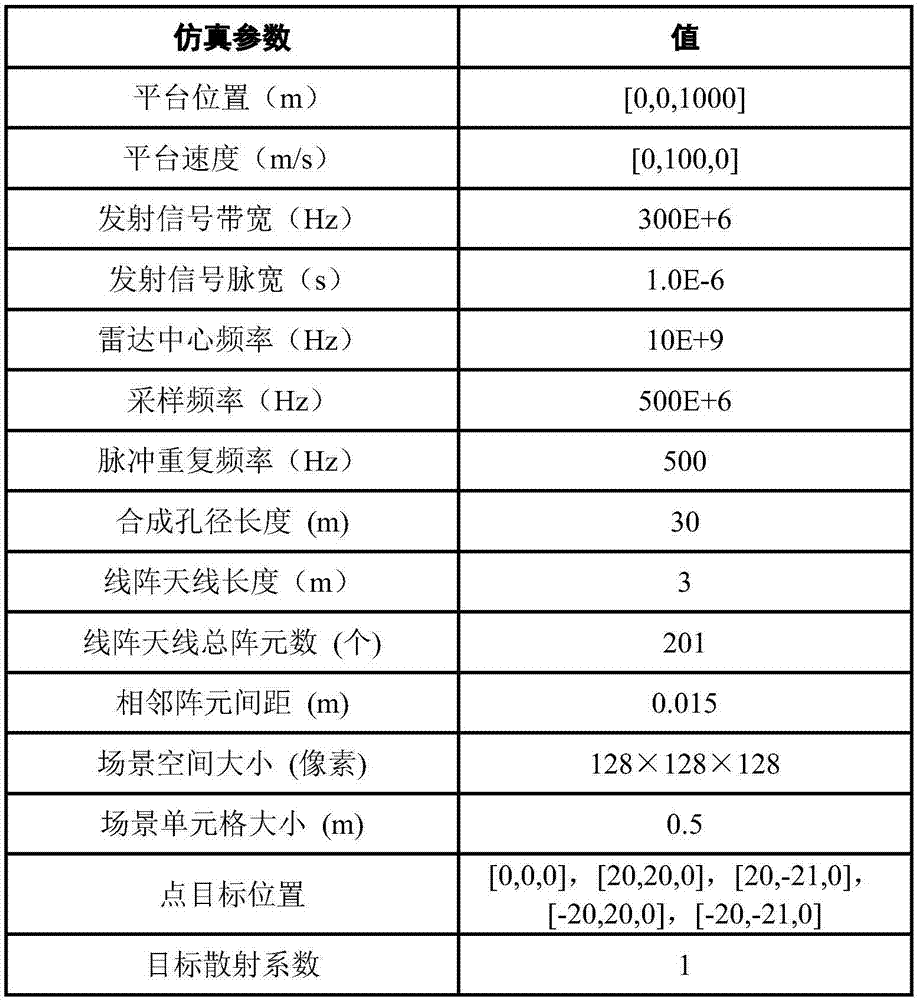
[0087] Step 1. Initialize the linear array SAR system parameters required for simulation:

[0088] Initialize the values ​​of the linear array SAR system parameters such as image 3 shown, including: motion platform velocity vector The total number of array elements of the linear array antenna N=201, the initial position vector of each array element of the linear array antenna Where n is the array element number of the nth linear array antenna, n=1,2,...,N, N=201, the length of the linear array antenna is L=3m, and the distance between adjacent array elements of the linear array antenna is d= 0.015m, radar center frequency f c =10GHz, the signal width B of the baseband signal of the radar transmitter r =300MHz, radar transmit signal pulse width T P =10 -6 s, frequency m...


PUM


Abstract

The invention provides a linear array SAR (Synthetic Aperture Radar) three-dimensional imaging method based on a threshold gradient tracking algorithm. The method comprises the steps of establishing a linear measurement model between linear array SAR original echo signals and a three-dimensional observation scene target scattering coefficient using a correlation among linear array SAR system parameters, motion platform parameters, space parameters of an observation scene target and original echo signals, and then reconstructing the observation scene target scattering coefficient using a TBGP (Total Blood Granulocyte Pool) method based on the signal linear measurement model. By using the contrast of maximum and minimum target scattering coefficients and the change rate of the target scattering coefficient as algorithm iteration termination conditions, the linear array SAR sparse imaging performance of a GP (Genetic Programming) algorithm under the condition that the sparsity of the observation scene is unknown is improved, the operation efficiency and the space storage efficiency are improved relative to an OMP (Orthogonal Matching Pursuit) algorithm, and the method can be applied in the fields of synthetic aperture radar imaging, earth remote sensing and the like.

Description

technical field [0001] The invention belongs to the technical field of radar, in particular to the technical field of synthetic aperture radar (SAR) imaging. Background technique [0002] Traditional Synthetic Aperture Radar (SAR) uses the linear motion of a single antenna to synthesize a one-dimensional virtual linear array antenna to obtain high resolution in the azimuth direction, and then uses pulse compression technology to obtain high resolution in the radar line of sight direction, thereby realizing two-dimensional imaging of the observation scene . However, the traditional 2D SAR mainly works in the side-view imaging mode, and there are terrain occlusion, shadow effects and top-bottom inversion problems in the side-view imaging, so the traditional 2D SAR cannot obtain satisfactory results in complex undulating terrain such as cities, mountains and canyons. Imaging results. The basic principle of 3D SAR is to synthesize a virtual two-dimensional area array antenna t...

Claims


Application Information

Patent Timeline
IPC IPC(8): G01S13/90
CPCG01S13/90G01S13/9004G01S13/904
Inventor 张晓玲周黎明左林电韦顺军田博坤
Owner UNIV OF ELECTRONICS SCI & TECH OF CHINA
Why Eureka
Try Eureka