Winding Unit

一种绕组单元、绕组部的技术,应用在电气元件、变压器/电感器线圈/绕组/连接、变压器等方向,能够解决难以制造可变电容器等问题,达到防止意外改变的效果

Active Publication Date: 2017-08-11
YAZAKI CORP
View PDF6 Cites 2 Cited by
  • Summary
  • Abstract
  • Description
  • Claims
  • Application Information

AI Technical Summary

Problems solved by technology

[0003] However, it is difficult to manufacture variable capacitors when using large-capacity capacitors

Method used


Image

  • Winding Unit
  • Winding Unit
  • Winding Unit

Examples


Embodiment Construction

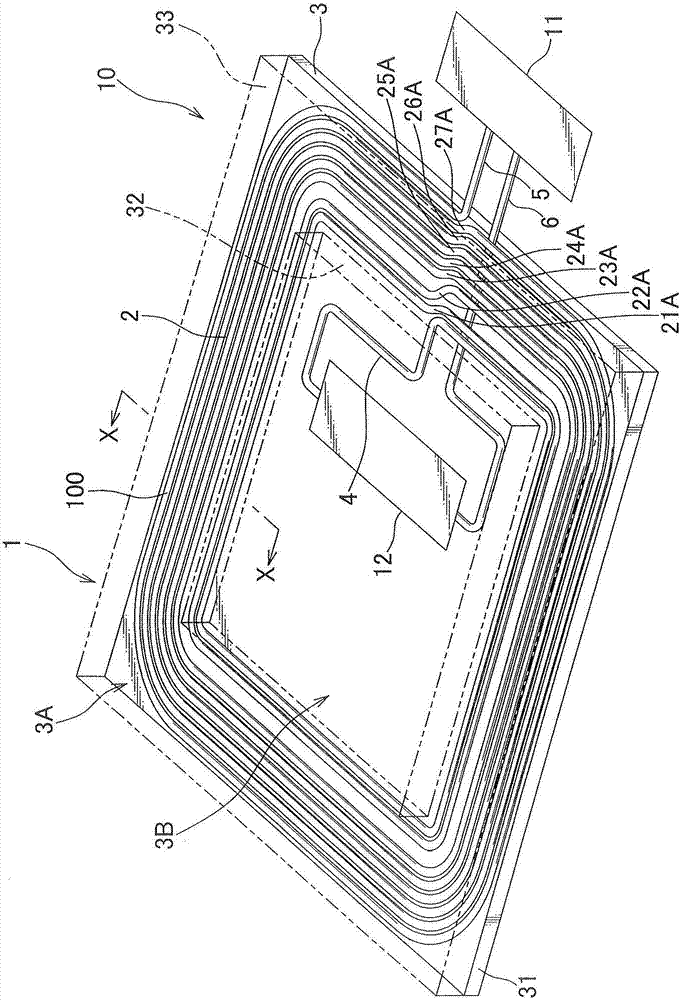
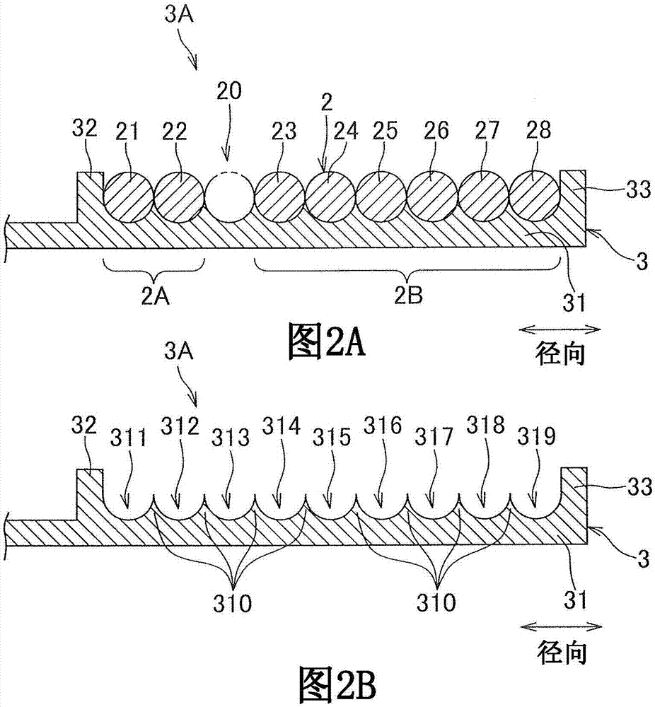
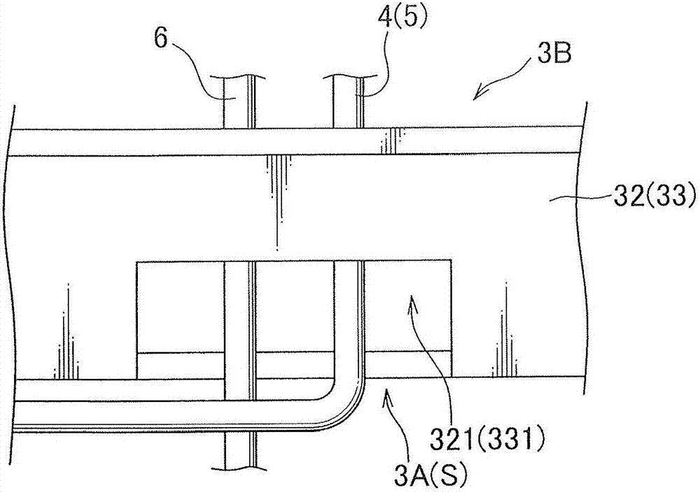
[0050] Hereinafter, embodiments of the present invention will be described with reference to the accompanying drawings. figure 1 is a perspective view showing the power supply unit in which the winding unit is arranged. Figure 2A is along the figure 1 The cross-sectional view of X-X line interception. FIG. 2B is a cross-sectional view showing a state where the winding portion is not arranged in FIG. 2A . image 3 It is a perspective view showing the electric wire drawing-out structure in a winding unit. Figure 4 is an image illustrating the inductance value of the winding portion for the position of the blank portion in the winding unit.

[0051] The winding unit 1 of the embodiment of the present invention is provided in a power supply unit 10 constituting a non-contact power supply device together with a power receiving unit not shown. Such as figure 1As shown, the winding unit 1 includes a winding part 2 and a casing 3 , and the casing serves as a storage part for acc...


PUM


Abstract

A winding unit including a case is provided. The case has a receiving space capable of housing at least one turn of a coil portion in addition to a winding portion in a radial direction. In case, a blank portion having a dimension of one turn of the coil portion in the radial direction is formed between the two coil portions next to each other in the winding portion. When manufacturing the winding unit, the blank portion can be formed in a suitable position, and the number of turns of the winding portion (the number of coil portion) does not need to change. Further, an inductance value of the winding portion can be adjusted with simply structure.

Description

technical field [0001] The invention relates to a winding unit arranged on a power supply unit or a power receiving unit of a non-contact power supply device. Background technique [0002] Generally, a resonance-type non-contact power supply device is known as a non-contact power supply device. In the resonant non-contact power supply device, a variable capacitor is used to adjust the resonant frequency. [0003] However, when a large-capacity capacitor is used, it is difficult to manufacture a variable capacitor. For this reason, it is desirable to omit the variable capacitor. Therefore, there is provided a structure having a mechanism for adjusting the number of turns of a coil in a contactless power supply device (for example, see Patent Document 1). In the coil of the non-contact power supply device described in Patent Document 1, one part is used to change the winding shape of the end portion, or to rewind a part of the coil to adjust the number of turns of the coil....

Claims


Application Information

Patent Timeline
Patent Type & Authority Applications(China)
IPC IPC(8): H01F38/14H01F27/02H01F27/30H02J50/12
CPCH01F27/02H01F27/306H01F38/14H01F27/006H01F27/2871H01F27/2823
Inventor 中原贵弘纳乌·安东尼·温布谷柳田曜石阪将夫
Owner YAZAKI CORP
Why Eureka
Try Eureka