Structural element for a fuselage cell structure of an aircraft, comprising at least one positioning aid

a technology of structural elements and aircraft, applied in the direction of distance measurement, height/levelling measurement, instruments, etc., can solve the problems of dimensional deviation, inability to reproduce, and considerable labour cost in so as to facilitate the measurement of a complete section and simplify the production of shell components

Inactive Publication Date: 2013-07-23
AIRBUS OPERATIONS GMBH
View PDF7 Cites 8 Cited by
  • Summary
  • Abstract
  • Description
  • Claims
  • Application Information

AI Technical Summary

Benefits of technology

[0005]The object of the invention is therefore to simplify the production of shell components, in particular the orientation of structural elements such as stringers and / or former segments on the skin panel of the shell component, and to facilitate measurement of a complete section once the individual components, for example in the form of fuselage shells, have been joined together.
[0008]the spatial orientation of a structural element equipped with the positioning aid in relation to a further component, for example a skin panel of a shell component, is simplified considerably. In addition, the absolute precision of the spatial orientation of the structural element in relation to the second component is improved significantly.
[0012]A further advantageous development of the structural element provides that the positioning aid can be connected to a target, in particular to a reflector, for determining the position using the laser measuring system.
[0017]The structural element formed according to the invention may, for example, be produced by the known “RTM method” (Resin Transfer Moulding method). In this case, a preformed reinforcement fibre arrangement is inserted into a two-part mould, for example, and then completely infiltrated with a curable plastics materials, in particular a two-component epoxy resin, with pressure and / or heat being applied. Carbon fibres which preferably extend in a force-flow-optimised manner in a plurality of layers laid one on top of another are generally used as a reinforcement fibre arrangement. The spatial shape of the component to be produced is predetermined very precisely by the mould during the RTM process, but tolerance deviations resulting from shrinkages caused by changes in temperature cannot be ruled out. It is possible to produce the positioning aid according to the invention by any method which uses a mould as a shaping tool. During the production process of the structural element, the positioning aid provided on the structural element may simultaneously be formed in one piece with the remaining structural element—similarly to a flash or a seam in injection moulding technology—for example by means of a small recess or a small indentation in the mould. For this reason, a separate process step is not required to produce the positioning aid. Since, during the production process of the structural element, the positioning aid is already formed simultaneously in a precisely defined spatial position, for example in the region of a central line of a stringer profile, subsequent measurement of the spatial position of the reinforcement profile is simplified and it is also possible to measure the spatial position of the structural element extremely precisely. The precise spatial position of the positioning aid can be determined very precisely on the basis of the known CAD data of the mould.
[0018]A further advantageous configuration of the invention provides that the at least one positioning aid can be removed from the structural element in a purely mechanical manner, in particular by grinding, rasping, milling, breaking, cutting or any combination thereof.
[0019]As a result, the positioning aid can easily be removed from the structural element after measuring, no as not to negatively affect subsequent production steps. Providing a small predetermined breaking point, for example, makes it still easier to break or shear off the positioning aid and as a result the positioning aid is removed at a defined point. At least three measuring points, i.e. at least three positioning aids, are always required for the correct measurement of a component in three-dimensional space.

Problems solved by technology

However, the production of composite components of this type is associated with dimensional deviations which are usually unavoidable for production-related reasons and also cannot be reproduced.
As a result, the production of shell components involves considerable labour costs.

Method used


Image

  • Structural element for a fuselage cell structure of an aircraft, comprising at least one positioning aid
  • Structural element for a fuselage cell structure of an aircraft, comprising at least one positioning aid
  • Structural element for a fuselage cell structure of an aircraft, comprising at least one positioning aid

Examples


Embodiment Construction

[0027]In the drawings, like constructional elements have the same reference numeral in each case.

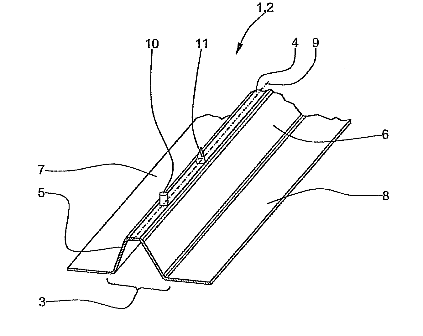
[0028]FIG. 1 shows a so-called Ω-stringer profile 2 as an embodiment of a structural element 1 according to the invention. The stringer profile 2 has a central portion 3 which has an approximately trapezoidal cross-sectional geometry. The central portion 3 has a horizontal top face 4, which is connected on each side to an inclined side face 5, 6. The side faces 5, 6 each finally transition into a horizontally extending flange 7, 8. Two positioning aids 10, 11, each having a different geometrical shape, are arranged one behind the other and offset from one another in the region of a central line 9 of the stringer profile 2.

[0029]The stringer profile 2 may for example, be produced by means of the RTM process using a carbon-fibre-reinforced epoxy resin. In contrast to the rest of the stringer profile 2, the positioning aids 10, 11 are not fibre-reinforced but preferably consist exclusively ...


PUM


Abstract

A structural element for a fuselage cell structure of an aircraft, in particular a stringer profile or an annular former segment, the structural element being made from a composite material, in particular from a carbon-fiber-reinforced epoxy resin. The structural element comprises at least one positioning aid for facilitating position determination by means of a measuring system. A laser measuring system and / or a tactile measuring system may be used as a measuring system. As a result of the reflector which can be attached to the positioning aid without clearance as a target for the laser measuring system, which is preferably a laser tracker, a spatial position of the structural element in relation to a further component can be determined very precisely and without contact. Following position determination and orientation of the structural element, the reflector can be removed from the positioning aid.

Description

CROSS-REFERENCE TO RELATED APPLICATIONS[0001]This application is a continuation of and claims priority to PCT International Application No. PCT / EP2009 / 065001 filed Nov. 11, 2009, which claims the benefit of and priority to U.S. Provisional Application No. 61 / 116,807, filed Nov. 21, 2008 and German Patent Application No. 10 2008 043 977.0, filed Nov. 21, 2008, the entire disclosures of which are herein incorporated by reference.FIELD OF THE INVENTION[0002]The invention relates to a structural element for a fuselage cell structure of an aircraft, in particular a stringer profile or an annular former segment, the structural element being made from a composite material, in particular from a carbon-fibre-reinforced epoxy resin.[0003]In modern aircraft construction, efforts are being made to make greater use of composite components, the composite components preferably being produced using carbon-fibre-reinforced epoxy resins. However, the production of composite components of this type is...

Claims


Application Information

Patent Timeline
Patent Type & Authority Patents(United States)
IPC IPC(8): G01C3/08
CPCB64C1/064
Inventor ARNOLD, RALPH
Owner AIRBUS OPERATIONS GMBH
Why Eureka
Try Eureka