Dividing device and dividing method of wafer

A wafer and chip technology, which is applied in the field of segmentation devices, can solve the problems of complex device structure, loose wrinkles, etc., and achieve the effect of simple device structure

Active Publication Date: 2017-08-11
DISCO CORP
View PDF8 Cites 4 Cited by
  • Summary
  • Abstract
  • Description
  • Claims
  • Application Information

AI Technical Summary

Problems solved by technology

[0007] However, since tension is applied in one direction of the tape when the tape is bonded to the ring frame, it is easy to place the tape opposite the wafer in the other direction perpendicular to the direction to which the tension is applied. become radially relaxed folds
In this case, in the method of Patent Document 2, since the tape between the outer periphery of the wafer and the inner periphery of the ring frame is uniformly heated, wrinkles cannot be sufficiently removed from the tape.
In the method of Patent Document 3, a structure for thermocompression-bonding the tape over the entire range in the circumferential direction is required, and the device structure becomes complicated.

Method used


Image

  • Dividing device and dividing method of wafer
  • Dividing device and dividing method of wafer
  • Dividing device and dividing method of wafer

Examples


Embodiment Construction

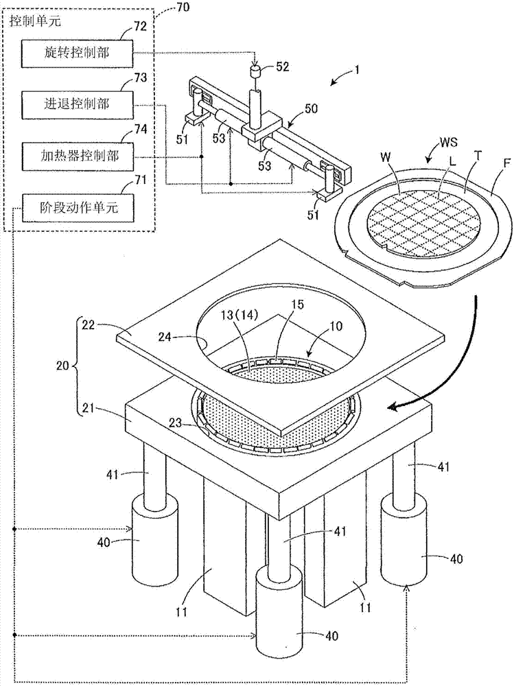
[0029] Hereinafter, a method for dividing a wafer using a dividing device will be described. figure 1 It is a perspective view of the division apparatus of this embodiment. In addition, the dividing device of this embodiment is not limited to figure 1 structure shown. Any structure may be used as long as the splitting device has a structure capable of removing wrinkles of the belt by heating while gradually releasing the expanded state of the belt.

[0030] Such as figure 1As shown, the dividing apparatus 1 is configured to divide the wafer W supported by the ring frame F through the tape T into individual chips by expanding the tape T. In addition, the dividing apparatus 1 is configured to release the expansion of the tape T while maintaining the chip interval, and to remove the gap between the outer periphery of the wafer W and the ring frame by heat shrink when the expansion of the tape T is released. The folds between the inner circumference of F. In this way, only th...


PUM


Abstract

To maintain the chip interval appropriately, by removing wrinkles from a tape by a simple device configuration. A dividing method of a wafer using a division device for dividing a wafer (W) supported on a ring frame (F) via a tape (T) into individual chips (C) at division start points along a division line has: a holding step of holding the ring frame on a ring frame holding section (20), and holding a wafer on the inside of the ring frame on a holding table (10); a division step of stretching the tape by separation of the holding table and the ring frame holding section, thus dividing the wafer at the division start points; and a rip separation step of separating a chip by thermally contracting the heating range of a heater (51) for thermally shrinking the stretched tape by a predetermined heating range, at a time, in the circumferential direction or radial direction between the outer periphery of the wafer and the inner periphery of the ring frame.

Description

technical field [0001] The present invention relates to a dividing device for dividing a wafer into individual chips along a planned dividing line and a method for dividing the wafer. Background technique [0002] In recent years, a method for increasing the number of chips to be obtained from one wafer by reducing the line width of the planned dividing line of the wafer has been known (for example, refer to Patent Document 1). In the method for dividing a wafer described in Patent Document 1, a modified layer along a line to be divided is formed inside the wafer by irradiating a laser beam which is transparent to the wafer. Thereafter, the tape attached to the ring frame is expanded by an expanding device or the like, whereby an external force is applied to the wafer attached to the upper surface of the tape, and the wafer is divided into individual chips starting from the modified layer. [0003] Although the gap between chips is enlarged by the stretching of the tape, wh...

Claims


Application Information

Patent Timeline
Patent Type & Authority Applications(China)
IPC IPC(8): H01L21/304H01L21/67H01L21/68
CPCH01L21/304H01L21/67011H01L21/67092H01L21/67098H01L21/68H01L2221/67
Inventor 植木笃
Owner DISCO CORP
Why Eureka
Try Eureka