Powder mixing device

A technology of mixing device and powder supply device, which is applied in the direction of mixer, mixing method, solid and solid mixing, etc., can solve the problems of insufficient powder mixing, inability to crush, uneven block powder, etc., and achieve simple equipment structure , fully mixed effect

Inactive Publication Date: 2017-08-15
浙江众鑫新材料科技有限公司
View PDF1 Cites 5 Cited by
  • Summary
  • Abstract
  • Description
  • Claims
  • Application Information

AI Technical Summary

Problems solved by technology

[0006] The purpose of the present invention is to address the deficiencies of the prior art and overcome the problem...

Method used


Image

  • Powder mixing device
  • Powder mixing device
  • Powder mixing device

Examples


Embodiment 1

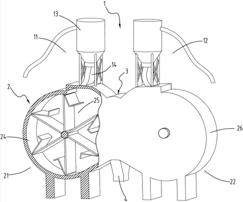
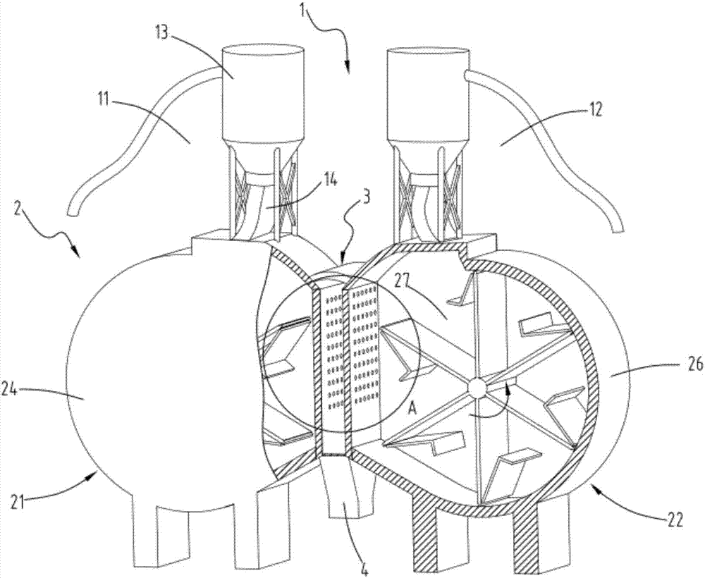
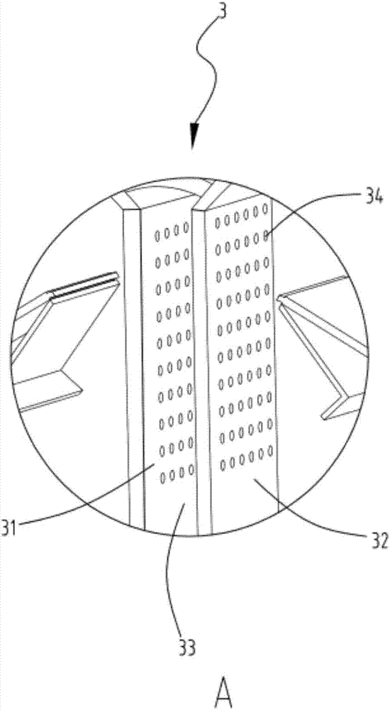
[0034] figure 1 It is a structural schematic diagram of a powder mixing device, figure 2 It is a schematic cross-sectional view of a powder mixing device, image 3 It is a schematic diagram of the enlarged structure of the powder mixing part, Figure 4 It is a schematic diagram of the structure of the powder throwing device, Figure 5 is the structural schematic diagram of the rotating part a, Figure 6 It is a schematic diagram of the enlarged structure of the pulverizing mechanism of the rotating part a, Figure 7 is the structural schematic diagram of the rotating part b, Figure 8 It is a schematic diagram of the structure of the powder support plate. Such as figure 1 , figure 2 , image 3 , Figure 4 , Figure 5 , Figure 6 , Figure 7 and Figure 8 As shown, a powder mixing device includes a powder supply part 1, which includes a powder supply device a11 and a powder supply device b12; a powder rejection part 2, which includes a first powder rejection unit...

Embodiment 2

[0043] Such as figure 1 , figure 2 , image 3 , Figure 4 , Figure 5 , Figure 6 , Figure 7 and Figure 8 As shown, the components that are the same as or corresponding to those in the first embodiment are marked with the corresponding reference numerals in the first embodiment. For the sake of simplicity, only the differences from the first embodiment will be described below. The difference between the second embodiment and the first embodiment is that the driving rods 401 and crushing rods 402 are arranged alternately along the width direction of the swinging plate 100, and the driving rods 401 and the driving rods 401 are not equidistantly arranged. The distance between the rod 401 and the driving rod 401 is 0.6cm-1.5cm.


PUM


Abstract

The invention relates to a powder mixing device which comprises a powder supply part, a powder throwing part and a powder mixing part, wherein the powder supply part comprises a powder supply device a and a powder supply device b; the powder throwing part comprises a first powder throwing unit and a second powder throwing unit; the first powder throwing unit is communicated with the powder supply device a; the second powder throwing unit is communicated with the powder supply device b; the powder is thrown to the direction of the second powder throwing unit by the first powder throwing unit; the powder is thrown to the direction of the first powder throwing unit by the second powder throwing unit; the powder mixing part comprises a powder outlet plate a arranged on one side of the first powder throwing unit and a powder outlet plate b arranged on one side of the second powder throwing unit; and a powder mixing space is formed between the powder outlet plate a and the powder outlet plate b. The problems that the powder is insufficient and non-uniform in mixing and massive powder cannot be ground in the mixing process are solved.

Description

technical field [0001] The invention relates to the technical field of mixing equipment, in particular to a powder material mixing device. Background technique [0002] Material mixing is a process in which particles with different physical and chemical properties are evenly distributed macroscopically by mechanical or fluid methods. Mixing uniformity is the degree of uniform distribution of components in the mixture, which refers to the closeness between the number of particles of a certain component contained in any unit volume or unit weight of the mixture and the average content, and is an important indicator for examining the quality of material mixing. . When choosing mixing equipment, the following properties should be considered: high mixing uniformity, no dead angle, and less material residue; short mixing time, high production efficiency, and matching with the entire unit; simple and strong structure, easy operation; ensuring mixing quality Under the premise, the...

Claims


Application Information

Patent Timeline
IPC IPC(8): B01F13/10B01F15/02B01F3/18
CPCB01F23/60B01F33/83B01F33/84B01F35/71805
Inventor 金勤生朱卫民
Owner 浙江众鑫新材料科技有限公司
Why Eureka
Try Eureka