Intelligent lamp
A lighting and intelligent technology, applied in lighting devices, cooling/heating devices of lighting devices, electric light sources, etc., can solve problems such as unreliable connections, long connection lines, troublesome assembly processes, etc., and achieve simple assembly, high production efficiency, The effect of eliminating the influence of shielding
- Summary
- Abstract
- Description
- Claims
- Application Information
AI Technical Summary
Problems solved by technology
Method used
Image
Examples
Embodiment 1
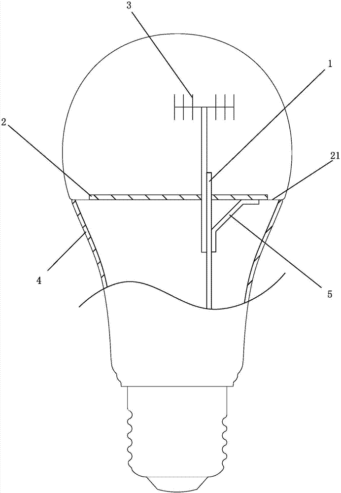
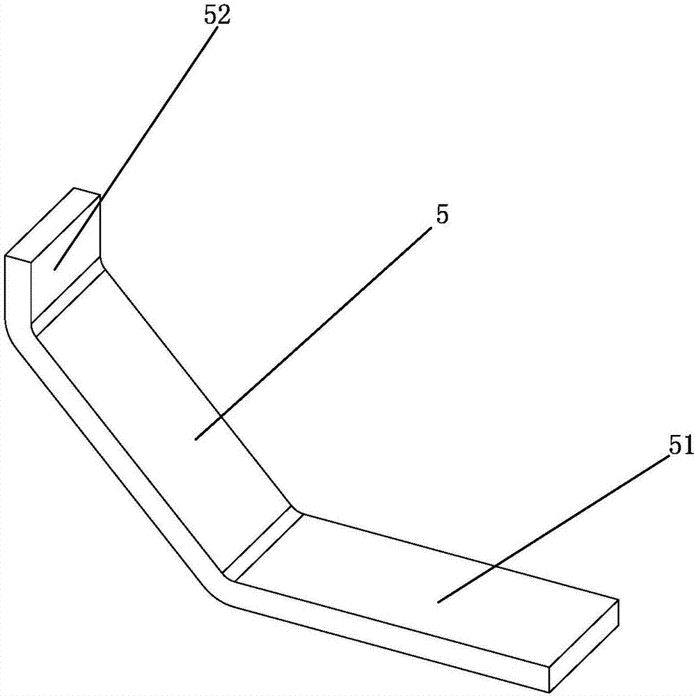
[0025] see Figure 1 to Figure 2 As shown, an intelligent lamp of the present invention includes an antenna 3, a light source board 2, a driving board 1 and a heat dissipation metal casing 4, the antenna 3 is connected to the driving board 1, and the driving board 1 is connected to the The light source board 2 is connected to control the work of the light source board 2; it also includes a metal elastic terminal, one end of the metal elastic terminal is welded to the ground end of the drive board 1, and the other end of the metal elastic terminal is connected to the The heat dissipation metal shells are connected with each other.
[0026] It also includes a heat dissipation backplane 21, which is assembled with the heat dissipation metal casing 4; the light source board 2 is fixedly mounted on the heat dissipation backplane 21.
[0027] The antenna 3 is made of metal or ceramic.
[0028] In this embodiment, the two ends of the metal elastic terminal 5 have a first hemming po...
Embodiment 2
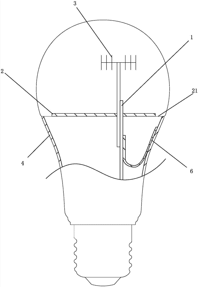
[0030] see Figure 3 to Figure 4 As shown, in this embodiment, the two ends of the metal elastic terminal 6 have a folded portion 61 and a first arc portion 62, the folded portion 61 is welded to the ground end of the drive board 1, and the arc The portion 62 elastically resists the heat dissipation metal casing 4 . The arc portion 62 is attached to the inner wall of the heat dissipation metal casing 4 to form a connection structure, so that the antenna 3 and the heat dissipation metal casing 4 are connected as a whole.
Embodiment 3
[0032] see Figure 5 to Figure 6 As shown, in this embodiment, the metal elastic terminal 7 includes a hem portion 71 and a first arc portion 72, the hem portion 71 is welded to the ground end of the driving board 1, and the first arc portion 72 elastically resists the heat dissipation metal shell 4 . The first arc portion 72 is in elastic contact with the heat dissipation backplane 21 , and is connected to the heat dissipation metal casing 4 through the heat dissipation backplane 21 . The first arc portion 72 is squeezed and fixed with the heat dissipation backplane 21 after being squeezed by the light source board 2, and is connected to the heat dissipation metal shell 4 through the heat dissipation backplane 21 to form a connection structure, so that the antenna 3 and the heat dissipation metal The casing 4 is connected as a whole.
PUM
 Abstract
Description
Claims
Application Information
 - R&D
- Intellectual Property
- Life Sciences
- Materials
- Tech Scout
- Unparalleled Data Quality
- Higher Quality Content
- 60% Fewer Hallucinations
Browse by: Latest US Patents, China's latest patents, Technical Efficacy Thesaurus, Application Domain, Technology Topic, Popular Technical Reports.
© 2025 PatSnap. All rights reserved.Legal|Privacy policy|Modern Slavery Act Transparency Statement|Sitemap|About US| Contact US: help@patsnap.com


