Lens, light source module and lighting device

A light source module and lens technology, applied in lighting devices, fixed lighting devices, components of lighting devices, etc., can solve the problems of small light output angle and poor uniformity, and achieve uniformity, high uniformity, and low cost effect

Inactive Publication Date: 2017-08-15
SUZHOU OPPLE LIGHTING
View PDF4 Cites 3 Cited by
  • Summary
  • Abstract
  • Description
  • Claims
  • Application Information

AI Technical Summary

Problems solved by technology

However, the existing lens is limited by its own shape and material properties, so that after the light emitted by the light source passes through the secondary light distribution of the lens, the light output angle is small, and the uniformity is not good, and it cannot effectively form a large-angle range of light output and high The effect of uniformity

Method used


Image

  • Lens, light source module and lighting device
  • Lens, light source module and lighting device
  • Lens, light source module and lighting device

Examples


Embodiment 1

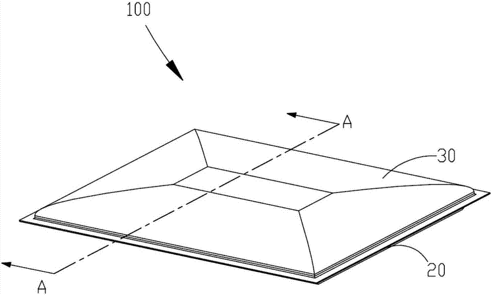
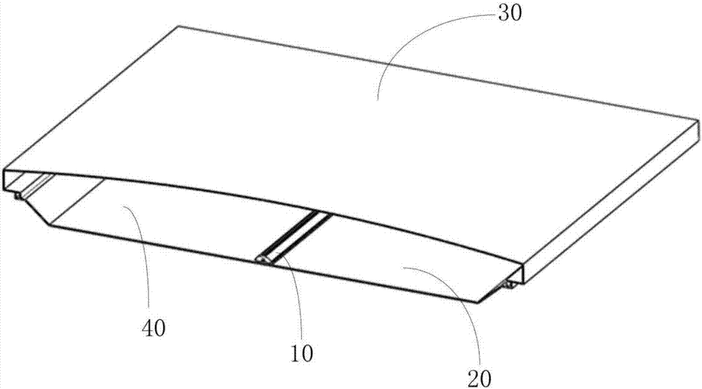
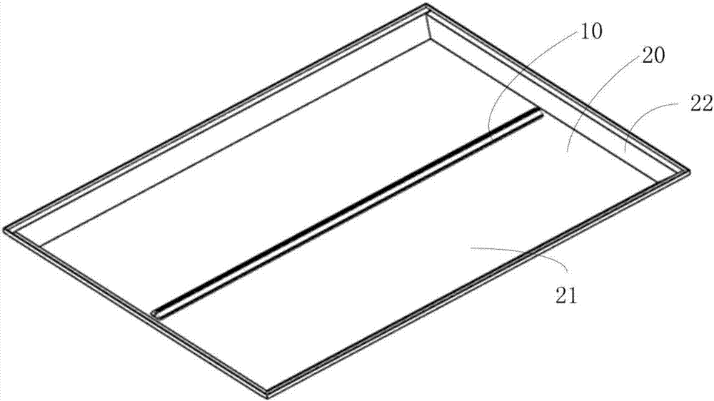
[0058] Figure 1 to Figure 3A lighting device 100 of the present invention is shown, including a chassis 20 , a mask 30 connected to the chassis 20 , and a light source module 10 fixed on the chassis 20 . Wherein, the mask 30 and the chassis 20 are connected to form a second receiving chamber 40 , and the light source module 10 is housed in the second receiving chamber 40 . The light source module 10 of the embodiment of the present invention can be used alone in lamps such as ceiling lamps or advertising light boxes.

[0059] In the following, each component and the connection relationship between the components in the lighting device 100 provided by Embodiment 1 of the present invention will be described in detail.

[0060] Such as Figure 1 to Figure 3 As shown, the chassis 20 is roughly in the shape of a cuboid, and has a flat bottom plate 21 and side walls 22 vertically extending from the bottom plate 21 . The width of the chassis 20 is greater than 550 mm, and it can ...

Embodiment 2

[0076] see Figure 10 As shown, Embodiment 2 of the present invention provides a lens 1a used in the lighting device 100 provided by Embodiment 1 of the present invention. The lens 1a is also linear, and its cross-sectional structure is the same as that of the lens 1 in Embodiment 1. structure is similar. The lens 1a has an inner surface 11a, an outer surface 12a, a bottom surface 13a, and a first cavity 110a for accommodating a light emitting unit (not shown). The wall of the first cavity 110a is the inner surface 11a of the lens 1a.

[0077] The only difference between the lens 1a and the lens 1 in the first embodiment is that the first light incident surface 111a of the lens 1a is a curved surface protruding toward the first receiving cavity 110a.

Embodiment 3

[0079] see Figure 11 As shown, Embodiment 3 of the present invention provides a lens 1b used in the lighting device 100 provided by Embodiment 1 of the present invention. The lens 1b is also linear, and its cross-sectional structure is the same as that of the lens 1 in Embodiment 1. structure is similar. The lens 1b has an inner surface 11b, an outer surface 12b, a bottom surface 13b, and a first cavity 110b for accommodating a light emitting unit (not shown). The wall of the first cavity 110b is the inner surface 11b of the lens 1b.

[0080] The only difference between the lens 1b and the lens 1 in Embodiment 1 is that the first light incident surface 111b of the lens 1b is a plane.


PUM


Abstract

The invention discloses a lens, a light source module and a lighting device. The lens includes a bottom surface, an inner surface, an outer surface, and a first accommodating cavity for accommodating light-emitting components, wherein the inner surface includes a first light incident surface and two oppositely arranged second light incident surfaces, and the first light incident surface The light surface is a curved surface or a plane, the bottom surface is adjacent to the second light incident surface, and the outer surface includes two first reflection surfaces forming a V-shaped structure, the first light exit surface on both sides of the first reflection surface, and the The second light-emitting surface adjacent to the first light-emitting surface, the light incident on the first light-incident surface is refracted and then collimated, and the second light-incident surface and the second light-emitting surface form a hyperboloid structure. The lens uses collimation plus total reflection structure and hyperboloid structure to superimpose the outgoing light to achieve a larger angle distribution of outgoing light and meet the requirements of high uniformity. At the same time, it can achieve more The uniform irradiation area of ​​the large-volume lamps reduces the cost.

Description

technical field [0001] The invention belongs to the technical field of lighting, and in particular relates to a lens, a light source module and a lighting device. Background technique [0002] Lenses that have been widely used in display or lighting fields such as TV backlights, ceiling lamps, and advertising light boxes need to have the dual characteristics of large-angle light output and uniform light output. However, the existing lens is limited by its own shape and material properties, so that after the light emitted by the light source passes through the secondary light distribution of the lens, the light output angle is small, and the uniformity is not good, and it cannot effectively form a large-angle range of light output and high The effect of uniformity. Contents of the invention [0003] The purpose of the present invention is to solve the above problems and provide a lens capable of achieving a large angle range and uniform light output. [0004] In order to ...

Claims


Application Information

Patent Timeline
Patent Type & Authority Applications(China)
IPC IPC(8): F21S8/00F21V5/04
CPCF21S8/00F21V5/04
Inventor 尹松邓诗涛李建国陈明姚斌斌
Owner SUZHOU OPPLE LIGHTING
Why Eureka
Try Eureka