
Asynchronous map construction and positioning system and method applied to service robots

A service robot and map construction technology, applied in the direction of instruments, surveying and mapping, navigation, navigation, etc., can solve the problems of small application range and high cost, and achieve the effect of low cost, high positioning accuracy and high reliability

Active Publication Date: 2020-02-07
黑龙江方真科技有限公司
View PDF6 Cites 0 Cited by
  • Summary
  • Abstract
  • Description
  • Claims
  • Application Information

AI Technical Summary

Problems solved by technology

[0004] The present invention aims to solve the problem that the existing ambient environment perception technology is easily affected by physical environmental factors such as light and humidity, and has a small application range and high cost; it proposes an asynchronous map construction and positioning system applied to service robots and method

Method used


Image

  • Asynchronous map construction and positioning system and method applied to service robots
  • Asynchronous map construction and positioning system and method applied to service robots
  • Asynchronous map construction and positioning system and method applied to service robots

Examples


specific Embodiment approach 1

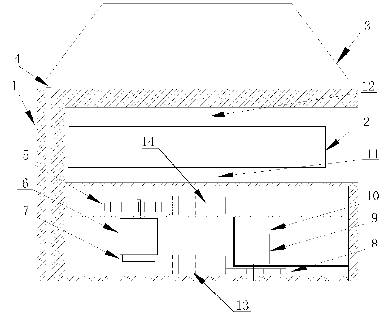
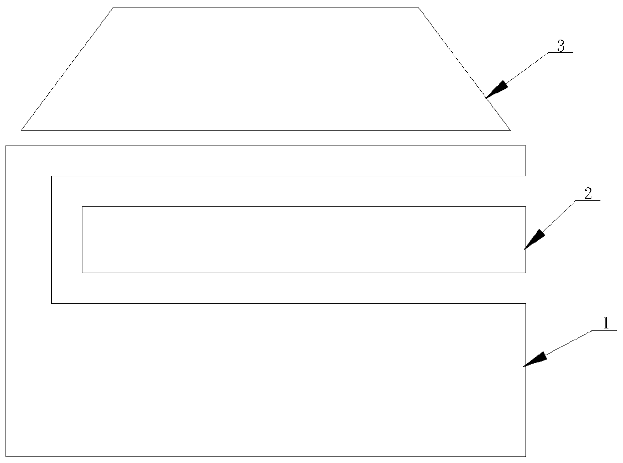
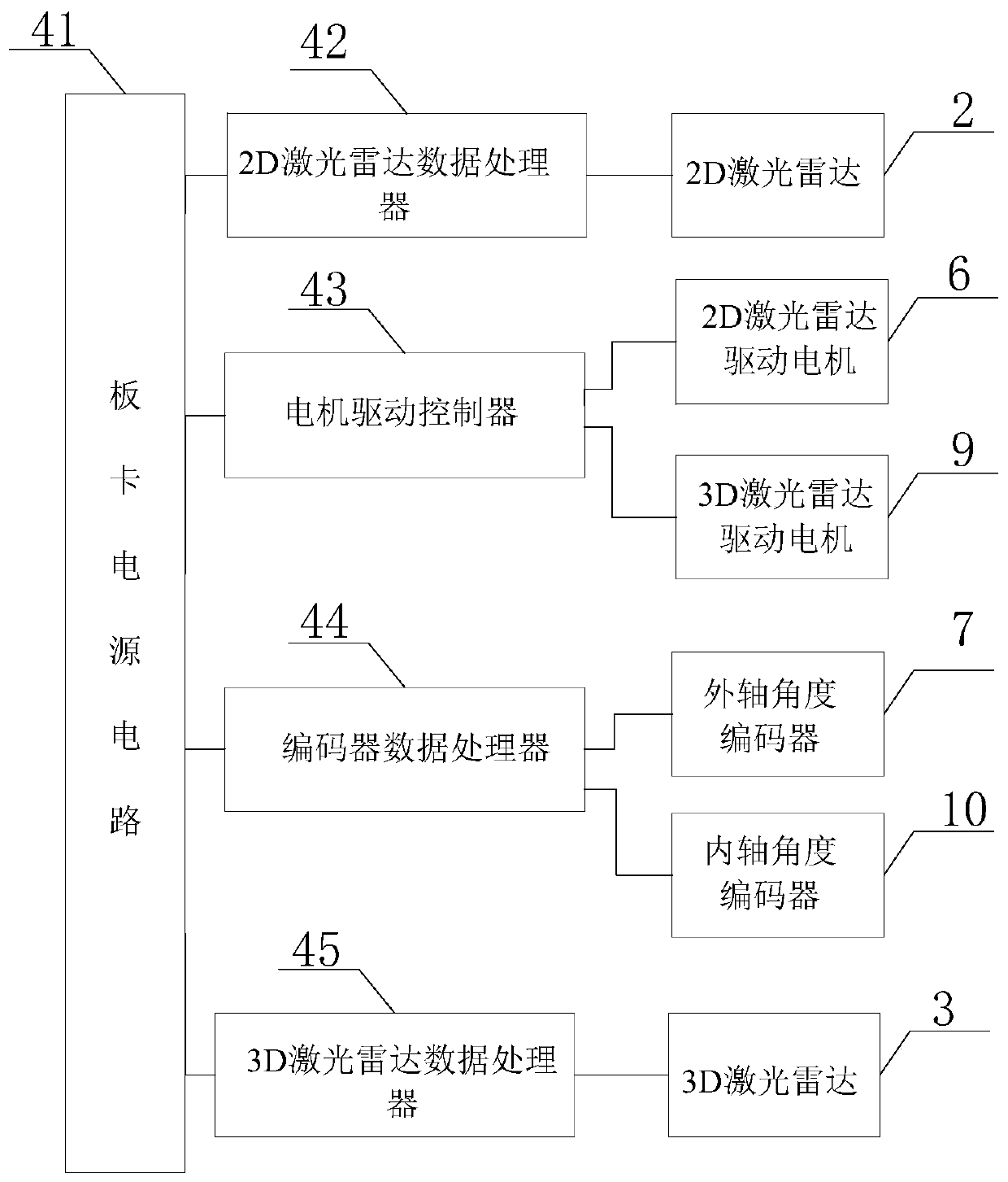
[0029] Specific implementation mode 1. Combination Figure 1 to Figure 3 Describe this embodiment. The asynchronous map construction and positioning system applied to service robots described in this embodiment includes a base 1, a 2D laser radar 2, a 3D laser radar 3, a board card 4, a transmission gear 5, 2D laser radar drive motor 6, external shaft angle encoder 7, No. 2 transmission gear 8, 3D laser radar drive motor 9, internal shaft angle encoder 10, rotary spindle external shaft 11, rotary spindle internal shaft 12, No. 3 transmission gear 14 and No. 4 transmission gear 13;

[0030] The base 1 is a cylinder with a hollow structure, and a rectangular scanning port is opened along the cylindrical surface of the base 1, and the 2D laser radar 2 is arranged in the rectangular scanning port; the top of the base 1 is a hollow frustum-shaped structure, and the 3D The laser radar 3 is arranged in the conical structure, and the 3D laser radar 3 is arranged on the upper side of ...

specific Embodiment approach 2

[0042] Embodiment 2. This embodiment is a further description of the asynchronous map construction and positioning system applied to service robots described in Embodiment 1. The ratio of the second transmission gear 8 to the fourth transmission gear 13 is 1:1 .

specific Embodiment approach 3

[0043] Specific embodiment three. This embodiment is a further description of the asynchronous map construction and positioning system applied to service robots described in specific embodiment one or two. The 3D laser radar 3 includes a surface lens, a linear laser transmitter, and a CMOS photosensitive Originals and polarizers;

[0044] The surface lens is embedded in the frustum-shaped structure at the top of the base 1, and the linear laser emitter, CMOS photosensitive element and polarizer are all arranged in the frustum-shaped structure of the base 1;

[0045] The laser signal of the linear laser transmitter is transmitted to the environment rotated by the 3D laser radar 3 through the surface lens, and the reflected light after the laser signal of the linear laser transmitter encounters an obstacle is incident on the polarizer through the surface lens again, and the reflected light After passing through a polarizer, it is incident on the photosensitive surface of the CMO...


PUM


Abstract

The invention discloses an asynchronous-type map constructing and positioning system and a method used for service robots, and belongs to the technical field of robot navigation. The method is used for solving problems in the prior art that conventional surrounding environment sensing technology is easily influenced by physical environment factors such as light and humidity, application range is small, and cost is relatively high. According to the asynchronous-type map constructing and positioning system, a transverse circular separating plate is arranged in a hollow structure of a pedestal; a 2D laser radar driving motor is arranged on the lower side of the transverse circular separating plate; an outer shaft angle coder is used for collecting the rotating speed of the 2D laser radar driving motor; the rotating shaft of the 2D laser radar driving motor is sleeved with a number 1 transmission gear; the number 1 transmission gear and a number 3 transmission gear mesh with each other; the outer side of a rotating main shaft outer shaft is sleeved with the number 3 transmission gear; the rotating main shaft outer shaft and a rotating main shaft inner shaft are arranged to be coaxial; the top of the rotating main shaft outer shaft and a 2D laser radar are fixedly connected; and the rotating main shaft inner shaft is fixedly connected with the lower surface of a 3D laser radar through the 2D laser radar. The asynchronous-type map constructing and positioning system and the method are suitable for robot navigation high precision positioning.

Description

technical field [0001] The invention belongs to the technical field of robot navigation. Background technique [0002] Laser navigation is to use the characteristics of laser linearity, small divergence angle, and energy concentration to perform multi-point precise measurement. Through the combined operation of data, the relative position of the device is calculated to achieve positioning. There are many ways of laser navigation, but there are mainly two mature and widely used laser navigation technologies at present. One is to use a laser reflector for positioning. The laser emitted by the laser transmitter is reflected by the reflector and received by the receiver. The position of the reflector at different positions is used to determine the current position of the device, and the relevant mathematical model is used for navigation guidance, which is characterized by high precision, but it cannot perceive the surrounding environment and requires other sensors to assist in s...

Claims


Application Information

Patent Timeline
Patent Type & Authority Patents(China)
IPC IPC(8): G01C21/32G01C21/20
CPCG01C21/206G01C21/32
Inventor 王祎民朱明煊杨一
Owner 黑龙江方真科技有限公司
Learn More