magnetic parts

A technology of magnetic parts and spacers, which is applied to transformer/inductor parts, electrical components, magnetic core/yoke, etc., can solve the problems of easy leakage magnetic flux and poor DC superposition characteristics, and achieve the suppression of leakage magnetic flux , DC superposition characteristics excellent effect

Active Publication Date: 2019-08-13
SUMIDA CORP
View PDF7 Cites 0 Cited by
  • Summary
  • Abstract
  • Description
  • Claims
  • Application Information

AI Technical Summary

Problems solved by technology

[0006] However, in the magnetic component disclosed in Patent Document 1, there is a problem that DC superposition characteristics are poor and leakage magnetic flux easily occurs.

Method used


Image

  • magnetic parts
  • magnetic parts
  • magnetic parts

Examples


Embodiment Construction

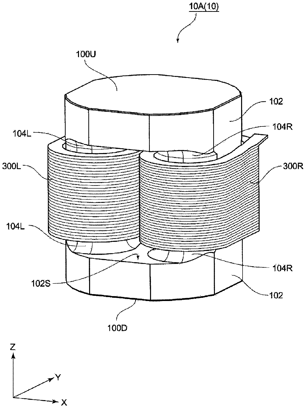
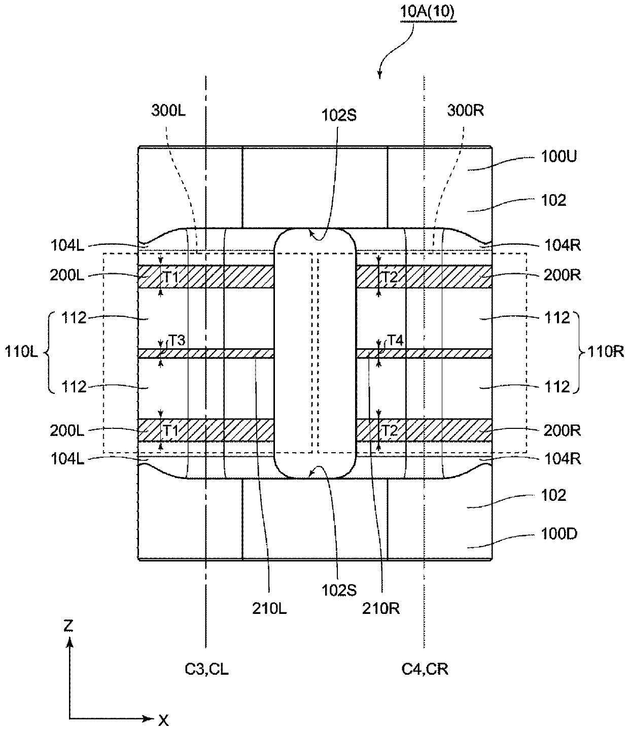
[0046] figure 1 and figure 2 It is a figure which shows an example of the magnetic component of this embodiment, and among them, figure 1 is the appearance stereogram, figure 2 is in figure 1 It is the front view which made the 1st coil and the 2nd coil transparent among the magnetic components of this embodiment shown. here, figure 2 The parts indicated by dotted lines are the first coil and the second coil. In addition, in Figure 1 ~ Figure 2 , the later image 3 as well as image 3 In each of the subsequent figures, the arrows XYZ shown in the figures are directions perpendicular to each other.

[0047] Such as figure 1 and figure 2 As shown, the magnetic component 10A ( 10 ) of this embodiment has a first ferrite core 100U, a second ferrite core 100D, a third ferrite core 110L, and a fourth ferrite core 110R as magnetic cores. The first ferrite core 100U and the second ferrite core 100D are respectively provided with two protrusions 104L, 104R on the side 1...


PUM


Abstract

A magnetic component is provided which has excellent DC overlay properties and is capable of suppressing leakage flux. The magnetic component includes: ferrite cores 100U, 100D each having two protruding components 104L, 104R; a ferrite core 110L disposed between one of the projecting members 104L of the ferrite cores 100U, 100D via the spacer 200L; a ferrite core 110R disposed via another spacer 200R between another of the protruding members 104R of the ferrite cores 100U, 100D; a coil 300L arranged so that the ferrite core 110L is located on an inner peripheral side thereof; and a coil 300R arranged so that the ferrite core 110R is located on an inner peripheral side thereof, the spacers 200L being located on the inner peripheral side of the coil 300L and the spacers 200R being located on the inner peripheral side of the coil 300R.

Description

technical field [0001] This invention relates to magnetic parts. Background technique [0002] In general, magnetic components used as reactors are constructed by combining simple I-shaped ferrite cores such as plate-shaped or column-shaped ferrite cores in consideration of ease of manufacture of magnetic components. For example, when paying attention to the ferrite core used in the magnetic component disclosed in Patent Document 1, the magnetic component has a first ferrite core and a second ferrite core arranged to face each other, and a spacer is interposed therebetween. A third ferrite core disposed between one end of the first ferrite core and one end of the second ferrite core, and the other end of the first ferrite core via a spacer and the fourth ferrite core between the other end of the second ferrite core. Also, each of the four ferrite cores has an I shape. In addition, in the magnetic component disclosed in Patent Document 1, a ferrite core having a higher res...

Claims


Application Information

Patent Timeline
Patent Type & Authority Patents(China)
IPC IPC(8): H01F37/00H01F27/24H01F27/30H01F27/26
CPCH01F37/00H01F3/14H01F27/255H01F27/346
Inventor 山田孝男上田穗积浅利知明
Owner SUMIDA CORP
Why Eureka
Try Eureka