Waste petroleum bucket cleaning device

A technology for cleaning devices and oil drums, which is applied in the directions of cleaning hollow objects, cleaning methods and utensils, cleaning methods using liquids, etc., and can solve the problems of time-consuming and laborious oil drums and low cleaning efficiency.

Pending Publication Date: 2017-08-18
郭钦
View PDF5 Cites 14 Cited by
  • Summary
  • Abstract
  • Description
  • Claims
  • Application Information

AI Technical Summary

Problems solved by technology

[0005] In order to overcome the present invention, there is no cleaning device for oil barrels, relying on manual cleaning of oil barrels, the manual cleaning of heavy oil barrels takes time and effort, and the shortcomings of low cleaning efficiency, the technical problem to be solved by the present invention is to provide a A waste oil barrel cleaning device that can clean oil barrels, save time and effort, and improve cleaning efficiency

Method used


Image

  • Waste petroleum bucket cleaning device
  • Waste petroleum bucket cleaning device
  • Waste petroleum bucket cleaning device

Examples


Embodiment 1

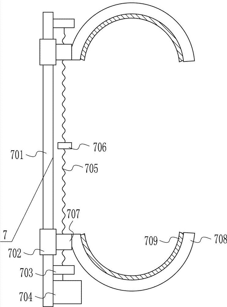
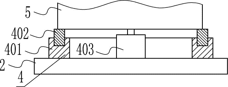
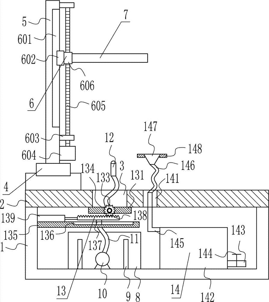
[0038] A kind of discarded oil barrel cleaning device, such as Figure 1-9 As shown, it includes a bracket 1, a horizontal plate 2, a rotating mechanism 4, a vertical plate 5, an up and down moving mechanism 6, a clamping device 7, a first water tank 8, a heating rod 9, a water pump 10, an outlet pipe 11 and a water nozzle 12, The top of the bracket 1 is connected with a horizontal plate 2 by means of bolt connection, the top left side of the horizontal plate 2 has a first port 3, and the top of the horizontal plate 2 on the left side of the first port 3 is provided with a rotating mechanism 4, and the rotating mechanism The rotating part of 4 is connected with a riser 5, the right side of the riser 5 is provided with an up and down movement mechanism 6, and the moving part of the up and down movement mechanism 6 is provided with a clamping device 7, and the left side of the inner bottom of the bracket 1 is connected by bolts The first water tank 8 is connected with the first ...

Embodiment 2

[0040] A kind of discarded oil barrel cleaning device, such as Figure 1-9 As shown, it includes a bracket 1, a horizontal plate 2, a rotating mechanism 4, a vertical plate 5, an up and down moving mechanism 6, a clamping device 7, a first water tank 8, a heating rod 9, a water pump 10, an outlet pipe 11 and a water nozzle 12, The top of the bracket 1 is connected with a horizontal plate 2 by means of bolt connection, the top left side of the horizontal plate 2 has a first port 3, and the top of the horizontal plate 2 on the left side of the first port 3 is provided with a rotating mechanism 4, and the rotating mechanism The rotating part of 4 is connected with a riser 5, the right side of the riser 5 is provided with an up and down movement mechanism 6, and the moving part of the up and down movement mechanism 6 is provided with a clamping device 7, and the left side of the inner bottom of the bracket 1 is connected by bolts The first water tank 8 is connected with the first ...

Embodiment 3

[0043] A kind of discarded oil barrel cleaning device, such as Figure 1-9 As shown, it includes a bracket 1, a horizontal plate 2, a rotating mechanism 4, a vertical plate 5, an up and down moving mechanism 6, a clamping device 7, a first water tank 8, a heating rod 9, a water pump 10, an outlet pipe 11 and a water nozzle 12, The top of the bracket 1 is connected with a horizontal plate 2 by means of bolt connection, the top left side of the horizontal plate 2 has a first port 3, and the top of the horizontal plate 2 on the left side of the first port 3 is provided with a rotating mechanism 4, and the rotating mechanism The rotating part of 4 is connected with a riser 5, the right side of the riser 5 is provided with an up and down movement mechanism 6, and the moving part of the up and down movement mechanism 6 is provided with a clamping device 7, and the left side of the inner bottom of the bracket 1 is connected by bolts The first water tank 8 is connected with the first ...


PUM


Abstract

The invention relates to a petroleum bucket cleaning device, in particular to a waste petroleum bucket cleaning device. According to the technical aim, according to the waste petroleum bucket cleaning device, a petroleum bucket can be cleaned, time and labor can be saved, and cleaning efficiency can be improved. In order to achieve the technical aim, the waste petroleum bucket cleaning device comprises a support, a cross plate, a rotary mechanism, a vertical plate, a vertical movement mechanism, a clamping device and the like. The top of the support is connected with the cross plate in a bolt connection manner, and a first through opening is formed in the left side of the top of the cross plate. A rotary mechanism is arranged at the top of the cross plate on the left side of the first through opening, and a rotary component of the rotary mechanism is connected with the vertical plate. The vertical movement mechanism is arranged on the right side face of the vertical plate. Water in a first water tank is heated through a heating bar, the hot water is sprayed into the petroleum bucket through a water spray head to clean the petroleum bucket, and therefore the petroleum bucket can be cleaned, and time and labor can be saved.

Description

technical field [0001] The invention relates to a cleaning device for petroleum oil barrels, in particular to a cleaning device for waste petroleum oil barrels. Background technique [0002] Petroleum, one of the main objects of geological exploration, is a viscous, dark brown liquid known as the "blood of industry." There are oil reserves in parts of the upper crust. The main component is a mixture of various alkanes, naphthenes and aromatic hydrocarbons. The oil-forming mechanism of petroleum has two theories of biosedimentary oil and petrochemical oil. The former is more widely accepted. It is believed that oil is formed by organisms in ancient oceans or lakes after a long evolution. It belongs to biosedimentary oil and is non-renewable. It is believed that petroleum is generated from the carbon in the earth's crust itself, has nothing to do with biology, and is renewable. Petroleum is mainly used as fuel oil and gasoline, and is also a raw material for many chemical i...

Claims


Application Information

Patent Timeline
Patent Type & Authority Applications(China)
IPC IPC(8): B08B9/08B08B9/093B08B3/10B08B13/00
CPCB08B9/08B08B3/10B08B9/0821B08B9/093B08B13/00
Inventor 不公告发明人
Owner 郭钦
Why Eureka
Try Eureka