Fin evaporator fin arrangement and pushing expansion all-in-one machine

A finned evaporator and integrated machine technology, applied in heat exchange equipment, metal processing equipment, feeding devices, etc., can solve the problems of low work efficiency, high labor cost, low efficiency, etc., and achieve small equipment footprint, The effect of high degree of automation and long service life

Active Publication Date: 2017-08-18
苏州优尼梅申工业机器人科技有限公司
View PDF5 Cites 9 Cited by
  • Summary
  • Abstract
  • Description
  • Claims
  • Application Information

AI Technical Summary

Problems solved by technology

[0002] Evaporators are commonly used equipment in petrochemical, electric power, nuclear power, refrigeration and other fields. In the preparation process of evaporators, the step of inserting fins is extremely critical, and the fins need to be strictly arranged to ensure high heat exchange efficiency. With the advancement of automation, the steps of fin insertion are gradually automated, but at present, in the automatic insertion process, the degree of automation is not high, and it often brings some problems: such as damage to the fins, during the fin insertion process , the force is unavoidable, but often because the fins are soft and easy to deform and damage; secondly, the flexibility of the equipment is not enough to carry out the process of inserting multiple types of fins at the same time; moreover, the equipment is not streamlined, the structure is complex, Low efficiency, inconvenient worker monitoring
[0003] Furthermore, the expansion tube needs to closely connect the aluminum tube and the fins with the fins arranged in the single-piece mold. In order to ensure the heat exchange effect of the evaporator, it is necessary to avoid the gap between the fins and the aluminum tubes and fins as much as possible. Loose, but in the traditional process, aluminum tubes and finned tubes are often expanded manually, which not only cannot ensure the tightness of the connection, but more importantly, the work efficiency is low and the labor cost is high

Method used


Image

  • Fin evaporator fin arrangement and pushing expansion all-in-one machine
  • Fin evaporator fin arrangement and pushing expansion all-in-one machine
  • Fin evaporator fin arrangement and pushing expansion all-in-one machine

Examples


Embodiment Construction

[0051] The following will clearly and completely describe the technical solutions in the embodiments of the present invention with reference to the accompanying drawings in the embodiments of the present invention. Obviously, the described embodiments are only some, not all, embodiments of the present invention. Based on the embodiments of the present invention, all other embodiments obtained by persons of ordinary skill in the art without creative efforts fall within the protection scope of the present invention.

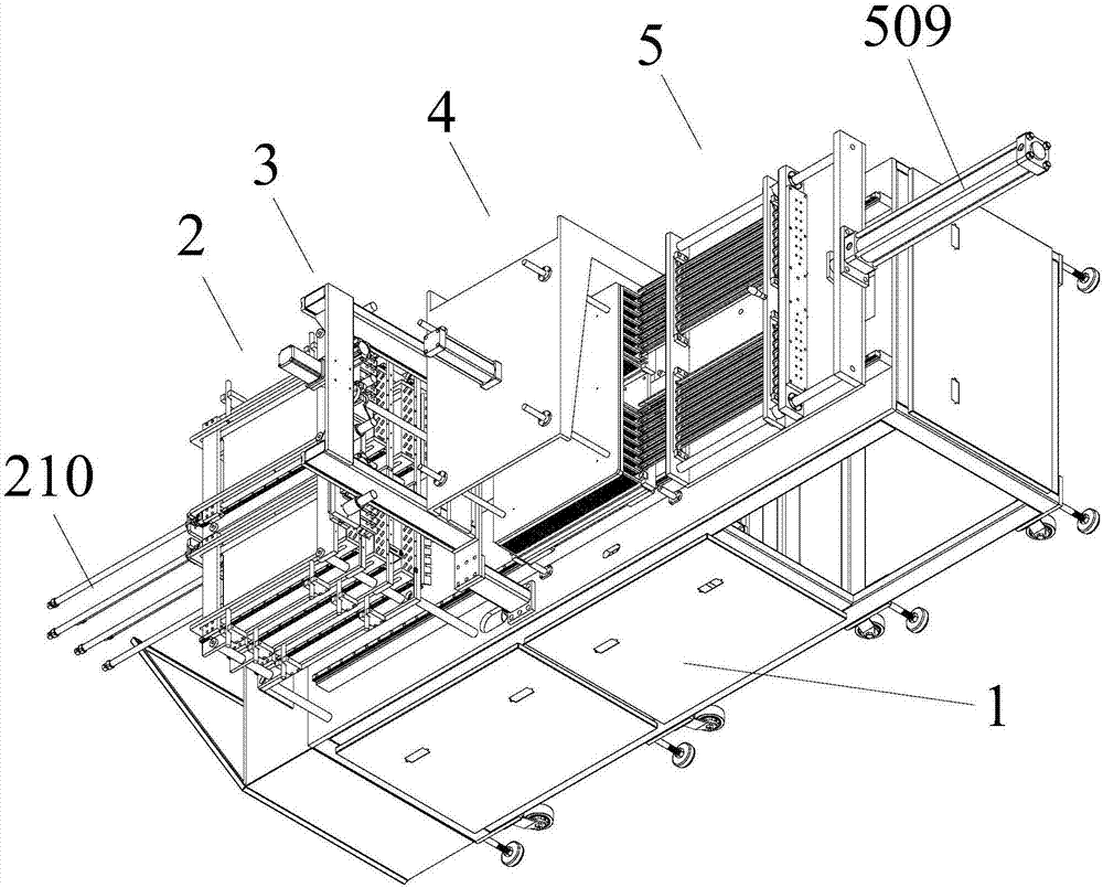
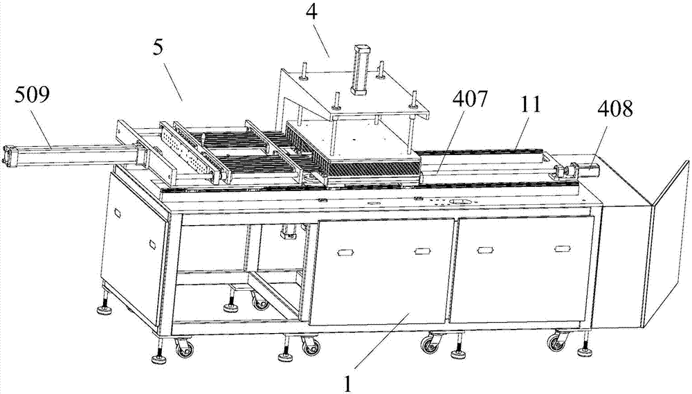
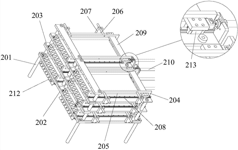
[0052] The present invention provides a finned evaporator all-in-one machine for pushing and expanding fins, which includes a frame 1. Two main line linear guide rails 11 placed horizontally and parallel are arranged on the table surface of the frame 1, and the two main line linear guide rails 11 are respectively fixed on the machine. On the table top of the frame 1, the main line linear guide rail 11 is provided with a fin feeding mechanism 2, a fin suction and rel...


PUM


Abstract

The invention discloses a fin evaporator fin arrangement and pushing expansion all-in-one machine which comprises a rack. A table surface of the rack is provided with two horizontally arranged main line linear guide rails which are arranged in parallel separately fixed to the table surface of the rack. Each main line linear guide rail is sequentially provided with a fin feeding mechanism, a fin adsorption and placing mechanism, a fin fixing mechanism and a pipe expansion mechanism according to the fin arrangement and pushing expansion procedures. According to the fin evaporator fin arrangement and pushing expansion all-in-one machine, the fin arrangement process and the pipe expansion process are conducted on the same equipment, the automation degree is high, and production efficiency is high; operation flexibility is higher, type changing is convenient, only several simple clamps and jigs need to be replaced, and the all-in-one machine can be suitable for various operation and is relatively small in equipment occupied area and convenient to monitor.

Description

technical field [0001] The invention relates to the technical field of evaporator industrial equipment, in particular to a finned evaporator push-expand integrated machine. Background technique [0002] Evaporators are commonly used equipment in petrochemical, electric power, nuclear power, refrigeration and other fields. In the preparation process of evaporators, the step of inserting fins is extremely critical, and the fins need to be strictly arranged to ensure high heat exchange efficiency. With the advancement of automation, the steps of fin insertion are gradually automated, but at present, in the automatic insertion process, the degree of automation is not high, and it often brings some problems: such as damage to the fins, during the fin insertion process , the force is unavoidable, but often because the fins are soft and easy to deform and damage; secondly, the flexibility of the equipment is not enough to carry out the process of inserting multiple types of fins at...

Claims


Application Information

Patent Timeline
Patent Type & Authority Applications(China)
IPC IPC(8): B21D53/08B21D43/02B21D43/18B21D43/00
CPCB21D43/003B21D43/027B21D43/18B21D53/08
Inventor 陈永祥
Owner 苏州优尼梅申工业机器人科技有限公司
Why Eureka
Try Eureka