
Riser for heat insulation casting

A riser and thermal insulation material technology, which is applied to casting molding equipment, casting molds, casting mold components, etc., can solve the problems of time-consuming, high production cost, waste of wood, etc., and achieve the effect of convenient use

Inactive Publication Date: 2017-08-18
邓锦志
View PDF5 Cites 0 Cited by
  • Summary
  • Abstract
  • Description
  • Claims
  • Application Information

AI Technical Summary

Problems solved by technology

[0003] In order to solve the problems of using wooden round risers, labor and time are wasted, wood is wasted, and the production cost is high, an iron riser is designed.

Method used


Image

  • Riser for heat insulation casting

Examples


Embodiment Construction

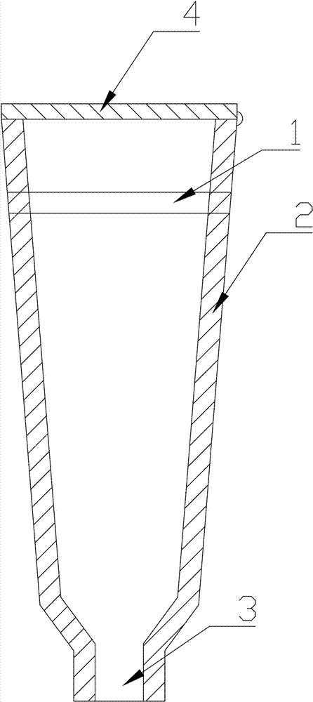
[0009] The present invention will be further described below in conjunction with the accompanying drawings and embodiments. As shown in the figure, a hoisting steel bar 1 is added to the upper part of the cavity iron riser body 2, and a positioning hole 3 is left at the bottom of the riser body 2. The cavity structure can save material and reduce weight. The hoisting steel bar 1 on the upper part of the riser body 2 is convenient for hoisting and connection. The positioning hole 3 at the bottom of the riser body 2 can enhance the accuracy of installation. The top of the riser is equipped with a cover 4 , the cover 4 is made of thermal insulation material, which plays a thermal insulation effect.


PUM


Abstract

The invention relates to the field of casting, in particular to an improvement on a riser of a casting. The special feature of the riser for thermal insulation casting is that a hoisting steel bar is added to the upper part of the cavity iron riser body, and a positioning hole is left at the bottom of the riser body. The cavity structure can save material and reduce weight. The hoisting steel bars on the upper part of the riser body are convenient for hoisting and connection. The positioning holes at the bottom of the riser body can enhance the accuracy of installation. The top of the riser is equipped with a cover. The technical effect of the present invention is that a convenient, safe and reliable riser can be realized by adopting the above technical solution.

Description

technical field [0001] The invention relates to the field of casting, in particular to an improvement on a riser of a casting. Background technique [0002] In the production of various castings in the foundry industry, wooden round risers of different sizes must be used to meet the needs of feeding, slag collection and gas outlet in the casting process. Due to the serious damage in the use process, it needs to be constantly replenished, which is labor-intensive, wastes wood, and increases production costs. Contents of the invention [0003] The present invention designs an iron riser to solve the problems of labor and time-consuming, wood waste and high production cost when using a wooden round riser. [0004] The technical solution of the present invention is a riser for thermal insulation casting, which is special in that a hoisting steel bar is added to the upper part of the hollow iron riser body, and a positioning hole is left at the bottom of the riser body. The c...

Claims


Application Information

Patent Timeline
IPC IPC(8): B22C9/08
CPCB22C9/088
Inventor 邓锦志
Owner 邓锦志
Learn More