Automatic wood cutting machine

A cutting machine and automatic technology, applied in the field of furniture manufacturing, can solve the problems of low processing efficiency, high risk, slipping, etc., and achieve the effect of good clamping effect, strong safety and accurate control

Inactive Publication Date: 2017-08-18
ZOY HOME FURNISHING CORP
View PDF7 Cites 19 Cited by
  • Summary
  • Abstract
  • Description
  • Claims
  • Application Information

AI Technical Summary

Problems solved by technology

This method is dangerous, the processing efficiency is low, and it is difficult to accurately control the size of the wood
When the wood cut by the traditional method is used as the table leg or chair leg of the furniture, it is easy to have different lengths of the four legs, which will cause the furniture to be plac

Method used


Image

  • Automatic wood cutting machine
  • Automatic wood cutting machine
  • Automatic wood cutting machine

Examples


Embodiment 1

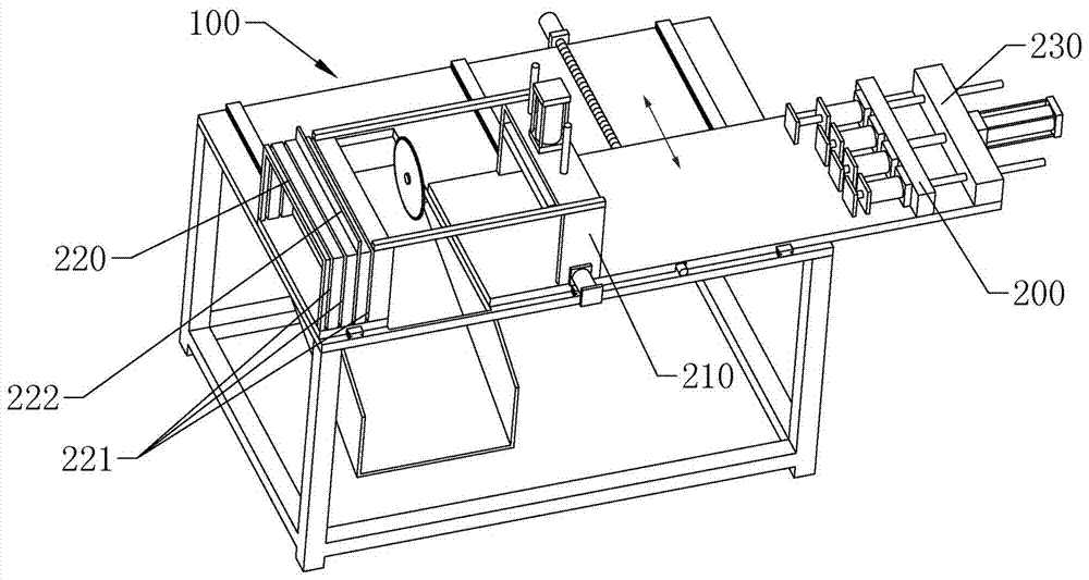
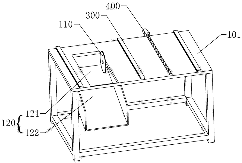
[0033] according to Figure 1~4 As shown in the figure, an automatic wood cutting machine includes: a fixed frame 100 and a movable frame 200, the movable frame 200 is arranged above the fixed frame 100, and a guide rail 300 and a screw mandrel 400 are arranged between the fixed frame 100 and the movable frame 200;

[0034] Fixture 100 comprises, top plate 101, cutting mechanism 110 and discharge mechanism 120, and discharge mechanism 120 comprises the blanking outlet 121 that is located on top plate 101 and blanking slide 122, and cutting mechanism 110 is the cutting machine that is fixed on top plate 101 below , and the slice top of the cutting machine is higher than the top of the top plate 101;

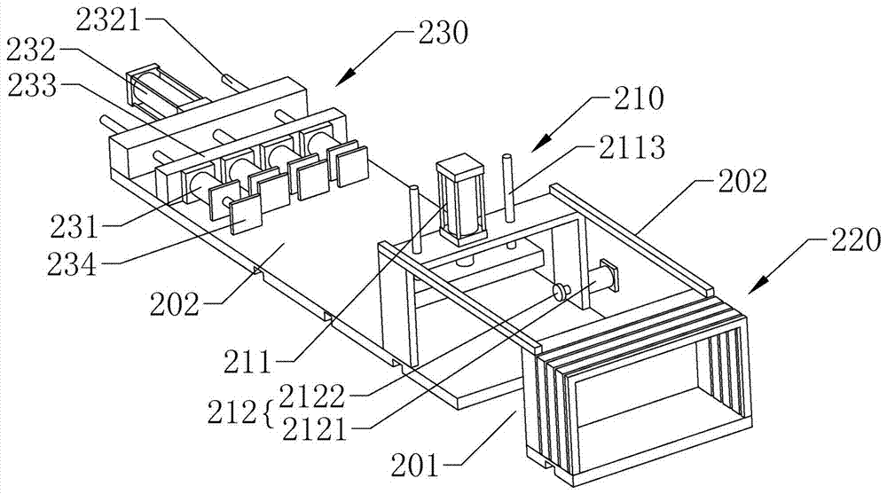
[0035] The movable frame 200 includes a cutting area 201, a clamping mechanism 210, a length positioning mechanism 220 and a pushing mechanism 230 positioned above the blanking outlet 121, the clamping mechanism 210, the length positioning mechanism 220 and the pushing mechanism 2...

Embodiment 2

[0041] The difference from the above-mentioned embodiment 1 is that, according to Figure 6 As shown, the movable frame 200 is provided with a top alignment mechanism 240 , and the top alignment mechanism 240 includes a pole 241 disposed on the side of the slide plate 203 close to the cutting area 201 and a baffle 242 hinged on the pole 241 . The pole 241 is provided with a shelf 2411 for preventing the baffle 242 , and the baffle 242 is provided with a bayonet 2421 away from the hinge, which is used for fixing the baffle 242 on the connecting rod 202 after it is lifted.

[0042] The unloading slide 122 includes a finished product passage 1221 and a waste passage 1222 , and the waste passage 1222 is located on a side of the unloading slide 122 close to the clamping mechanism 210 .

[0043]When this embodiment is in use, the difference from Embodiment 1 is that in the process of flushing the head, the wood is pushed against the baffle plate 242, and then the whole movable frame...


PUM


Abstract

The invention relates to the field of furniture manufacturing, in particular to an automatic wood cutting machine. The automatic wood cutting machine comprises a fixed frame and a movable frame. The movable frame is arranged above the fixed frame. A guide rail and a lead screw are arranged between the fixed frame and the movable frame. The fixed frame comprises a top plate, a cutting mechanism and a discharging mechanism. The discharging mechanism comprises a discharging outlet formed in the top plate and a discharging slide. The cutting mechanism is a cutting machine body fixed to the lower portion of the top plate. The top of a cutting blade of the cutting machine body is higher than the top of the top plate. The movable frame comprises a cutting area located above the discharging outlet, a clamping mechanism, a length positioning mechanism and a pushing mechanism. The clamping mechanism, the length positioning mechanism and the pushing mechanism are sequentially arranged. The cutting area is arranged between the clamping mechanism and the length positioning mechanism. The clamping mechanism is connected with the top of the length positioning mechanism through a connecting rod. The clamping mechanism is connected with the bottom of the pushing mechanism through a sliding plate.

Description

technical field [0001] The invention relates to the field of furniture manufacturing, in particular to an automatic wood cutting machine. Background technique [0002] In the process of furniture processing, wood cutting machines are often used to cut multiple pieces of furniture wood. Common cutting machines are usually fixed on the cutting table, and then the wood is manually pushed to cut. This method is dangerous, the processing efficiency is low, and it is difficult to accurately control the size of the wood. When the wood cut by the traditional method is used as the table leg or chair leg of the furniture, it is easy to have different lengths of the four legs, which will cause the furniture to be placed unstable and affect the use of the furniture. For example, a splitting wood cutting machine disclosed in CN201410374251.6 adopts an automatic method to cut wood, but it still has the following shortcomings. Accurate, and second, the head is not flat before the first ...

Claims


Application Information

Patent Timeline
IPC IPC(8): B27B5/06B27B5/29B27B25/00B27B29/02B27G3/00B27G19/02
CPCB27B5/06B27B5/29B27B25/00B27B29/02B27G3/00B27G19/02
Inventor 曹勇
Owner ZOY HOME FURNISHING CORP
Why Eureka
Try Eureka