Condenser and refrigeration system

A condenser and condensation chamber technology, applied in evaporators/condensers, refrigerators, refrigeration components, etc., can solve the problems of single oil return outlet, affect heat exchange efficiency, unfavorable oil return, etc., and achieve the goal of improving oil separation efficiency Effect

Pending Publication Date: 2017-08-18
GREE ELECTRIC APPLIANCES INC OF ZHUHAI
View PDF7 Cites 8 Cited by
  • Summary
  • Abstract
  • Description
  • Claims
  • Application Information

AI Technical Summary

Problems solved by technology

[0004] In the prior art, in the condenser with a built-in oil separation device, due to the limited oil separation space, it is difficult to improve the separation efficiency of the oil separation device
In addition, the oil return outlet of the eccentrically arranged oil separation device is single, and the installation inclination will have a negative impact on the overall oil return of the unit, and the eccentric structure affects the heat transfer efficiency of the condenser by affecting the flow field

Method used


Image

  • Condenser and refrigeration system
  • Condenser and refrigeration system
  • Condenser and refrigeration system

Examples


no. 1 example

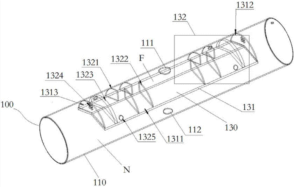
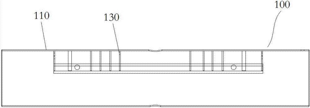
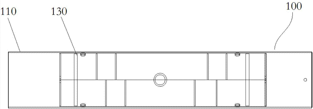
[0072] Figure 1 to Figure 5 A structural diagram of the condenser 100 according to the first embodiment of the present invention is shown.

[0073] like Figure 1 to Figure 5 As shown, the condenser 100 includes a housing 110 , a condenser tube bundle 120 and an oil separation device 130 . The condenser tube bundle 120 is disposed in the condenser chamber N along the front-rear direction. The casing 110 has a refrigerant inlet 111 that communicates with the oil separation chamber F and a refrigerant outlet 112 that communicates with the condensation chamber N.

[0074] The oil separation device 130 includes an inner partition 131 and an oil separation structure 132 . like Figure 1 to Figure 5 As shown, in the first embodiment, the refrigerant inlet 111 is located in the middle of the housing 110 in the front-rear direction, and the oil separation device 130 includes two oil separation structures 132 arranged on the front and rear sides of the refrigerant inlet 111 respec...

no. 2 example

[0090] Figure 6 to Figure 10 The structure of the condenser 200 of the second embodiment of the present invention is shown.

[0091] like Figure 6 to Figure 10 As shown, the difference between the second embodiment and the first embodiment is that, in the second embodiment, the four baffles include two upper baffles 2321 arranged on the upper side of the oil separation chamber F and two upper baffles 2321 arranged on the oil separation chamber F. The two lower baffles 2322 on the lower side of F, the upper baffles 2321 and the lower baffles 2322 are alternately arranged.

[0092] Suppose the cross-sectional area of ​​the oil separation chamber F is S, the area of ​​the upper baffle 2321 is S3, and the area of ​​the lower baffle 2322 is S4, then preferably, 0.3S≤S3≤0.8S, 0.3S≤S4≤0.8 S. For example, both S3 and S4 may be 0.5S.

[0093] For the parts not described in the second embodiment, reference may be made to the related contents of the other embodiments.

no. 3 example

[0095] Figure 11 The structure of the oil separation device 330 of the condenser according to the third embodiment of the present invention is shown.

[0096] like Figure 11 As shown, the difference between this embodiment and the first embodiment is that, in this embodiment, the oil separation device 330 only includes an oil separation structure 332 located at the front side of the refrigerant inlet. In this embodiment, the rear sealing plate 3312 is completely enclosed to prevent the refrigerant from entering the condensation chamber without oil separation.

[0097] For the parts not described in the third embodiment, reference may be made to the related contents of the other embodiments.


PUM


Abstract

The invention discloses a condenser and a refrigeration system. The condenser comprises a shell, a condensation tube bundle and an oil separation device. The oil separation device comprises an inner separation plate and an oil separation structure. The shell is divided by the inner separation plate into a condensation chamber and an oil separation chamber located above the condensation chamber. The condensation tube bundle is arranged in the condensation chamber in the front-back direction. The shell is provided with a refrigerant inlet communicated with the oil separation chamber and a refrigerant outlet communicated with the condensation chamber. The oil separation structure comprises a baffle plate, a filtering screen, a refrigerant communicating opening and an oil return opening, and the baffle plate and the filtering screen are arranged in the oil separation chamber. A refrigerant enters the oil separation chamber through the refrigerant inlet and sequentially passes through the baffle plate and the filtering screen, oil in the refrigerant is separated, and the separated refrigerant enters the condensation chamber through the refrigerant communicating opening to be condensed; and the condensed refrigerant flows out of the refrigerant outlet, and separated oil liquid flows out of the oil separation chamber through the oil return opening. According to the condenser and the refrigeration system, the oil separation efficiency of the refrigerant is high.

Description

technical field [0001] The invention relates to the technical field of refrigeration, in particular to a condenser and a refrigeration system. Background technique [0002] The oil separation device plays the role of separating the fine oil droplets in the gaseous refrigerant in the refrigeration unit. The purpose of setting the oil separation device is to prevent the oil droplets in the exhaust gas of the compressor from entering the condenser, and then entering the evaporator, which affects the overall energy efficiency of the unit. [0003] In the prior art, the development of external oil separation devices such as vertical oil separation devices and horizontal oil separation devices is relatively mature. develop. The installation of the built-in oil separation device not only needs to consider the separation efficiency, but also takes into account design factors such as space layout and system oil return. [0004] In the prior art, in a condenser with a built-in oil ...

Claims


Application Information

Patent Timeline
IPC IPC(8): F25B39/04F25B43/02
CPCF25B39/04F25B43/02F25B2500/18
Inventor 杨旭峰洪丽胡东兵胡海利
Owner GREE ELECTRIC APPLIANCES INC OF ZHUHAI
Why Eureka
Try Eureka