Rate gyro tester

A rate gyroscope and tester technology, used in instruments, measuring devices, etc., can solve problems such as inability to test and reproduce faults on the ground, and achieve the effects of improving efficiency and quality, rapid determination and repair, and simple external connections

Inactive Publication Date: 2017-08-18
HARBIN
View PDF5 Cites 0 Cited by
  • Summary
  • Abstract
  • Description
  • Claims
  • Application Information

AI Technical Summary

Problems solved by technology

[0002] At present, our factory does not have this kind of calibration equipment, so we cannot test the various functions and detailed technical indicators of this speed gyroscope before installation, and install it directly; The fault is still the fault of the on-board circuit or other cross-linking equipment, which can only be solved on the plane, and the fault phenomenon cannot be reproduced on the ground

Method used


Image

  • Rate gyro tester
  • Rate gyro tester

Examples


Embodiment Construction

[0011] The present invention will be described in detail below in conjunction with the accompanying drawings.

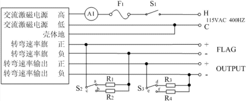
[0012] like figure 1 As shown, a rate gyro tester consists of SPST switch S1, SPDT switches S2, S3, fuse F1, ammeter A1, test holes FLAG+, FLAG-, OUTPUT+, OUTPUT-, and resistors R1, R2, R3 , R4 composition.

[0013] The high end of the 115V 400 Hz AC power supply is connected to the high end of the AC excitation power supply of the rate gyro plug through the SPST switch S1 and the fuse F1 through the ammeter A1, and the low end of the 115V 400 Hz AC power supply is connected to the low end of the AC excitation power supply of the rate gyro plug and the shell The body is connected to the ground to provide the working power for the rate gyro. The test hole FLAG+ is connected to the positive end of the rate gyro plug turning rate flag, and at the same time connected to the c point of the single pole double throw switch S2, the a point of S2 is connected to one end of ...


PUM


Abstract

The invention relates to a rate gyro tester, which comprises a single-pole single-throw switch (S1), a single-pole double-throw switch (S2), a single-pole double-throw switch (S3), a fuse (F1), an ammeter (A1), a positive testing hole (FLAG+), a negative testing hole (FLAG-), a positive output testing hole (OUTPUT+), a negative output testing hole (OUTPUT-), a first resistor (R1), a second resistor (R2), a third resistor (R3) and a fourth resistor (R4), wherein the first single-pole single-throw switch (S1) controls a power supply and is connected to the fuse (F1) and the ammeter (A1) in series, the middle position of the second single-pole double-throw switch (S2) is connected to the positive testing hole (FLAG+), the double throw terminals of the second single-pole double-throw switch (S2) are respectively corresponding to the first resistor (R1) and the second resistor (R2), the first resistor (R1) and the second resistor (R2) are connected to the negative testing hole (FLAG-), the middle position of the third single-pole double-throw switch (S3) is connected to the positive output testing hole (OUTPUT+), the double throw terminals of the third single-pole double-throw switch (S3) are respectively corresponding to the third resistor (R3) and the fourth resistor (R4), and the third resistor (R3) and the fourth resistor (R4) are connected to the negative output testing hole (OUTPUT-).

Description

technical field [0001] The invention belongs to the field of aircraft failure testing, in particular to a rate gyro tester. Background technique [0002] At present, our factory does not have this kind of calibration equipment, so we cannot test the various functions and detailed technical indicators of this speed gyroscope before installation, and install it directly; The fault is still the fault of the on-board circuit or other cross-linking equipment, which can only be solved on the plane, and the fault phenomenon cannot be reproduced on the ground. Contents of the invention [0003] The technical problem to be solved in the present invention: [0004] It is a speed gyro tester that can comprehensively test various performance indicators of the product, adopts external general-purpose equipment, reduces costs, simplifies design, has higher reliability of the tester, and avoids repeated construction of the laboratory. [0005] Technical scheme of the present invention:...

Claims


Application Information

Patent Timeline
Patent Type & Authority Applications(China)
IPC IPC(8): G01C25/00
Inventor 宁春玲刘春磊王威梁霄杨志
Owner HARBIN
Why Eureka
Try Eureka