Balancing weight installation position measurement device in dynamic balance test

A technology of installation position and measurement device, applied in the field of dynamic balance test, can solve the problems of increased workload, affected work efficiency, low installation angle accuracy, etc., and achieves the effect of improving accuracy and improving work efficiency

Pending Publication Date: 2017-08-18
SHANDONG IRON & STEEL CO LTD
View PDF5 Cites 0 Cited by
  • Summary
  • Abstract
  • Description
  • Claims
  • Application Information

AI Technical Summary

Problems solved by technology

However, the bisection angle of the coupling is prone to deviation, which leads to low accuracy of the installation angle and requires multiple adjustments, resulting in increased workload and more frequent equipment shutdowns, which affects work efficiency

Method used


Image

  • Balancing weight installation position measurement device in dynamic balance test
  • Balancing weight installation position measurement device in dynamic balance test
  • Balancing weight installation position measurement device in dynamic balance test

Examples


Embodiment Construction

[0027] An embodiment of the present invention provides a device for measuring the installation position of a counterweight in a dynamic balance test, which improves the accuracy of measuring the installation position of the counterweight and further improves work efficiency.

[0028] In order to make the purpose, technical solutions and advantages of the embodiments of the present invention clearer, the technical solutions in the embodiments of the present invention will be clearly and completely described below in conjunction with the drawings in the embodiments of the present invention. Obviously, the described embodiments It is a part of embodiments of the present invention, but not all embodiments. Based on the embodiments of the present invention, all other embodiments obtained by persons of ordinary skill in the art without making creative efforts belong to the protection scope of the present invention.

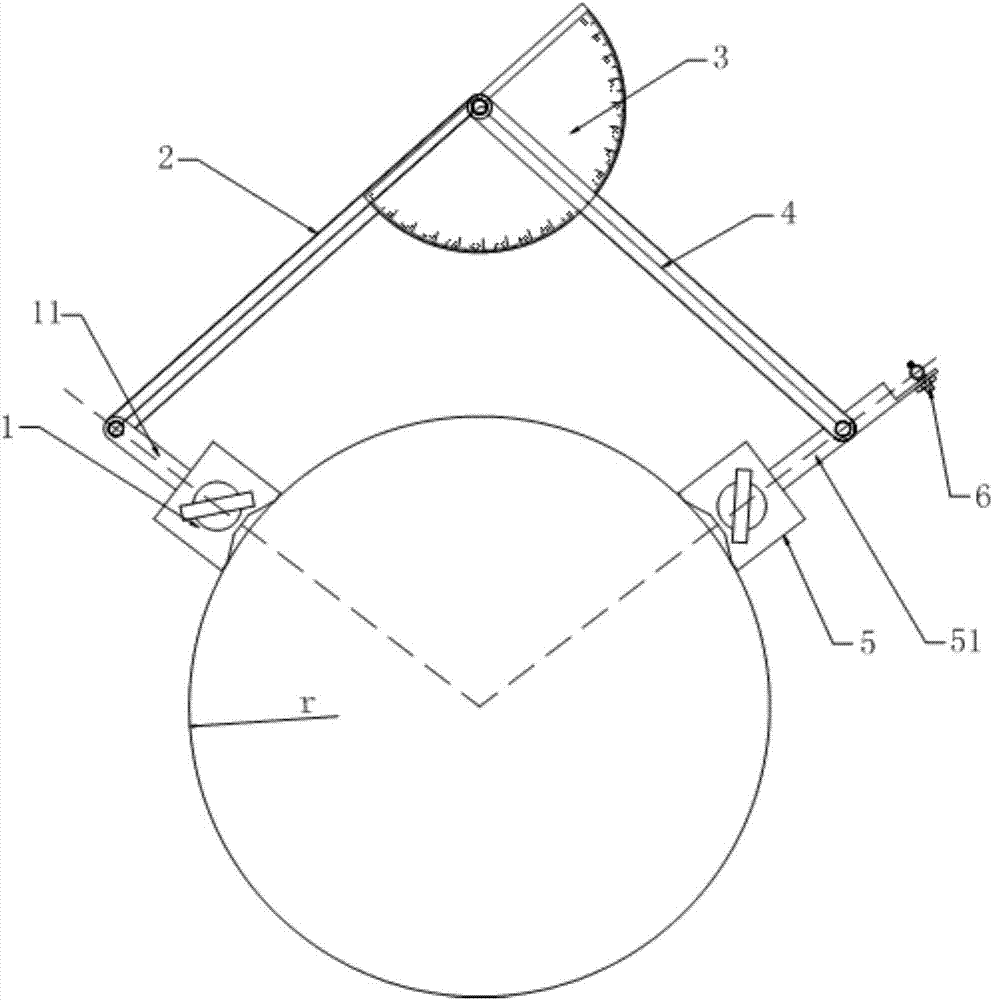
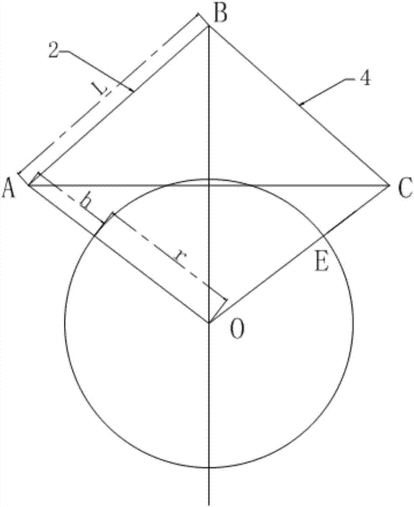
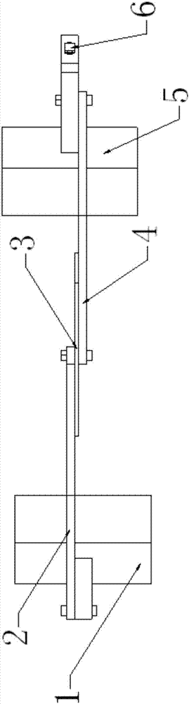
[0029] Please refer to the attached Figure 1-3 , the counterweig...


PUM


Abstract

The invention provides a balancing weight installation position measurement device in a dynamic balance test. The device comprises a reference position base fixed at a reference position of a rotating shaft of a rotating part, an installation position base fixed at an installation position of the rotating shaft, a fist connecting rod, a second connecting rod and an angle measurement mechanism; the reference position base is equipped with a reference upright rod disposed in a radial direction of the rotating shaft; the installation position base is equipped with a measurement upright rod disposed in a radial direction of the rotating shaft, the axis of the measurement upright rod and the axis of the reference upright rod both pass the circle center of the same cross section of the rotating shaft, and a length of a connection line between the circle center and one end, away from the circle center, of the measurement upright rod is same as a length of a connection line between the circle center and one end, away from the circle center, of the reference upright rod; one end of the first connecting rod is hinged with the reference upright rod; one end of the second connecting rod is hinged with the other end of the first connecting rod, and the other end of the second connecting rod is hinged with the measurement upright rod; and the angle measurement mechanism measures an inclined angle between the first and second connecting rods. A fixation position of the installation position base is determined through an adjustment for the inclined angle between the first and second connecting rods, accuracy of balancing weight installation position measurement is improved, and then working efficiency is improved.

Description

technical field [0001] The invention relates to the technical field of dynamic balance tests, in particular to a device for measuring installation positions of counterweights in dynamic balance tests. Background technique [0002] During the on-site dynamic balance test, according to the measurement of the instrument, it is necessary to install counterweights on rotating parts such as impellers or fans. [0003] The current method of measuring the installation angle of the counterweight generally uses a cursor to stick on the shaft of the rotating part, and through the monitoring of the photoelectric sensor, the installation angle α that needs to be added with the weight is fed back. Since the rotating parts are generally installed in the casing, the installation position needs to be determined on site, because the measuring surface and the cross-section of the rotating parts that need to be equipped with weights are parallel to each other. Install the counterweight at the ...

Claims


Application Information

Patent Timeline
Patent Type & Authority Applications(China)
IPC IPC(8): G01M1/14G01B21/00
CPCG01B21/00G01M1/14
Inventor 尹峰魏颖颖蒋超友张剑张帅刘喆付兆升
Owner SHANDONG IRON & STEEL CO LTD
Why Eureka
Try Eureka