Rotation detection device
A technology of rotation detection and equipment, applied in the direction of measuring device, conversion sensor output, instrument, etc., can solve the problem of magnetic flux density that cannot be applied to magnetic sensor, and achieve the effect of preventing false detection
- Summary
- Abstract
- Description
- Claims
- Application Information
AI Technical Summary
Problems solved by technology
Method used
Image

Examples
Embodiment
[0030] (Structure of Rotation Detection Device)
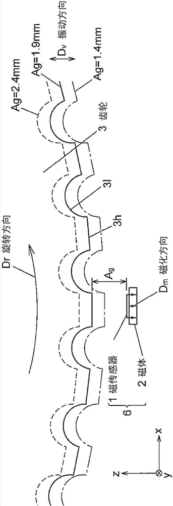
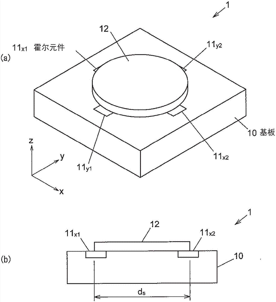
[0031] figure 1 is a side view showing an example of the structure of the rotation detection device according to the embodiment. figure 2 (a) and (b) are a perspective view and a sectional view showing the configuration of the magnetic sensor 1 , respectively.
[0032] The rotation detection device 6 includes a magnetic sensor 1 arranged with a gap Ag from the teeth 3 h of the gear 3 and a magnet 2 arranged on the back of the magnetic sensor 1 , where the magnetization direction is defined as Dm. In particular, the solid line indicates that the gear 3 is arranged to have a specified air gap (Ag=1.9mm), while the dashed line (Ag=2.4mm) and the dotted line (Ag=1.4mm) indicate that the gear 3 has vibration due to the gear 3 while changing the air gap Ag.
[0033] Such as figure 2 As shown in (a) and (b), the magnetic sensor 1 includes: a flat substrate 10 having a thickness in the z direction;
[0034] Hall element 11 mount...
PUM
 Abstract
Description
Claims
Application Information
 - R&D
- Intellectual Property
- Life Sciences
- Materials
- Tech Scout
- Unparalleled Data Quality
- Higher Quality Content
- 60% Fewer Hallucinations
Browse by: Latest US Patents, China's latest patents, Technical Efficacy Thesaurus, Application Domain, Technology Topic, Popular Technical Reports.
© 2025 PatSnap. All rights reserved.Legal|Privacy policy|Modern Slavery Act Transparency Statement|Sitemap|About US| Contact US: help@patsnap.com