
Drying device

A drying device and drying technology, applied in optics, instruments, photographic plate-making process of pattern surface, etc., can solve problems such as affecting the quality of vapor-deposited products, and achieve the effect of reducing rebound airflow

Active Publication Date: 2017-08-18
BOE TECH GRP CO LTD +1
View PDF9 Cites 1 Cited by
  • Summary
  • Abstract
  • Description
  • Claims
  • Application Information

AI Technical Summary

Problems solved by technology

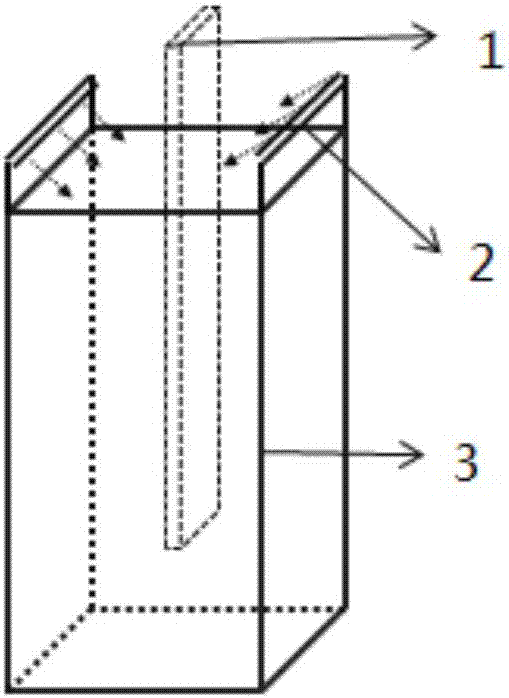
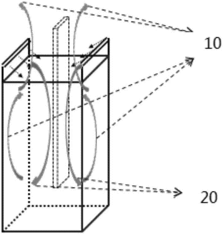
The bottom of the current Dry Bath (drying chamber) 3 is a closed structure (only one hole for draining), such as figure 1 and figure 2 As shown, when the air knife (AK) 2 blows downward to dry the mask plate 1, due to the almost closed structure of the lower part of the drying chamber 3, the air 20 blown downward by the air knife 2 is saturated. At this time, an upward airflow 10 will be formed, and the upward airflow 10 will drive the Particle (dust) deposited on the bottom of the drying chamber 3, and the dust driven by the upward airflow 10 will be deposited on the surface of the mask plate 1, and the mask plate with dust deposited 1 When placed in the evaporation chamber for evaporation, it will affect the quality of the evaporation product

Method used


Image

  • Drying device
  • Drying device
  • Drying device

Examples


Embodiment Construction

[0026] The features and principles of the present invention will be described in detail below in conjunction with the accompanying drawings, and the embodiments are only used to explain the present invention, not to limit the protection scope of the present invention.

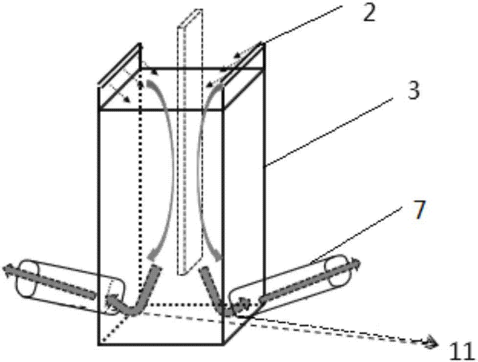
[0027] Such as image 3 As shown, this embodiment provides a drying device for drying a mask plate, including a drying chamber 3 , and an air knife 2 is provided at the port of the drying chamber 3 .

[0028] The side wall of the drying chamber 3 near the bottom of the drying chamber 3 is provided with an air outlet 11 for discharging the airflow generated by the air knife 2 .

[0029] An air outlet 11 is set at the bottom of the drying chamber 3, and the suction effect of the air outlet 11 is utilized to change the direction of the air flow (change the original rebound air flow), so that the air flow flows out from the air outlet 11 provided, image 3 The direction of the middle arrow is the flow direction of...


PUM


Abstract

The invention relates to a drying device used for drying a mask. The drying device comprises a drying chamber and is characterized in that air blades are arranged at the port of the drying chamber, and air outlets used for discharging air flow generated by the air blades are arranged at positons, close to the bottom of the drying chamber, of the lateral walls of the drying chamber. The drying device has the advantages that the generation of rebounded air flow is reduced by the air outlets, so that the influence of dust raised by the rebounded air flow on the mask is reduced, and product evaporation yield is increased.

Description

technical field [0001] The invention relates to the technical field of liquid crystal product production, in particular to a drying device. Background technique [0002] The fine metal mask (FMM Mask) mode is to vapor-deposit OLED (Organic Light-Emitting Diode, Organic Light-Emitting Diode) material on the LTPS (low temperature polysilicon) backplane according to a predetermined procedure by evaporation, and use the pattern on the mask plate to Evaporate red, green and blue organic matter to the specified position. The bottom of the current Dry Bath (drying chamber) 3 is a closed structure (only one hole for draining), such as figure 1 with figure 2 As shown, when the air knife (AK) 2 blows downward to dry the mask plate 1, due to the almost closed structure of the lower part of the drying chamber 3, the air 20 blown downward by the air knife 2 is saturated. At this time, an upward airflow 10 will be formed, and the upward airflow 10 will drive the Particle (dust) deposi...

Claims


Application Information

Patent Timeline
IPC IPC(8): G03F1/82
CPCG03F1/82
Inventor 林治明尹志杨成发王震唐富强黄俊杰
Owner BOE TECH GRP CO LTD
Learn More