Calculating method for limited area of wind-driven rain amount

A limited area and calculation method technology, applied in the field of wind engineering, can solve the problems of huge raindrop trajectory calculation amount, single raindrop trajectory calculation amount, etc., and achieve the effect of reducing the number of raindrop trajectory, reducing the calculation amount, and accurate collection rate distribution

Inactive Publication Date: 2017-08-18
BEIHANG UNIV
View PDF0 Cites 0 Cited by
  • Summary
  • Abstract
  • Description
  • Claims
  • Application Information

AI Technical Summary

Problems solved by technology

And because the calculation of single raindrop trajectory is also very large, the current wind-driven rain calculation method requires a huge amount of calculation of raindrop trajectory

Method used


Image

  • Calculating method for limited area of wind-driven rain amount
  • Calculating method for limited area of wind-driven rain amount
  • Calculating method for limited area of wind-driven rain amount

Examples


Embodiment 1

[0041] Example 1: Calculation of three-dimensional accessibility index wind field collection rate.

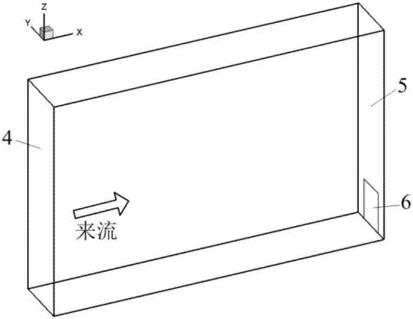
[0042] The calculation domain is a three-dimensional barrier-free index wind field, which is 300m long, 50m wide, and 200m high, and corresponds to the x-y-z three-axis directions. Such as figure 2 As shown, the inlet boundary 4 of the calculation domain is given the incoming flow velocity type, and the expression is as follows:

[0043]

[0044] In the formula, u represents the local wind speed; u 0 Represents the reference speed, take 10m / s; h represents the local height; h 0 It represents the reference height, which is 10m; α is the index, which is 0.176.

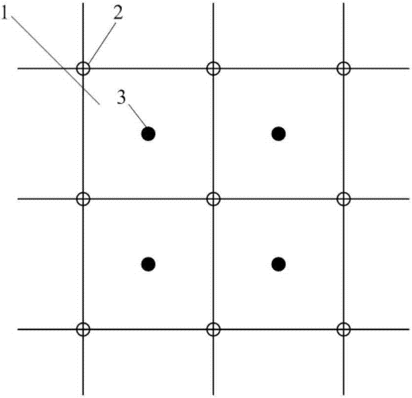
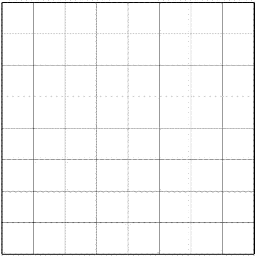
[0045] The plane 6 to be calculated for the collection rate is located at the exit boundary 5, and the width and height of the plane 6 to be calculated are 10m. Divide the plane 6 to be calculated into 8×8 finite areas, image 3 The limited area division is given. The chosen reconstruction function has the follo...

Embodiment 2

[0049] Example 2: Calculation of collection rate on the windward side of a three-dimensional square building. The length, width and height of the building are all 10m. Such as Figure 7 In the calculation area of ​​the three-dimensional square building shown, the incoming flow velocity type is given at the entrance boundary 7 of the calculation area, the expression is the same as formula (2), and the reference velocity u 0 =10m / s, reference height h 0 = 10m, exponent α = 0.15. Divide the windward side 8 of the three-dimensional square building into 20×20 limited areas, and the form of the selected reconstruction function is as follows:

[0050]

[0051] In the formula,

[0052]

[0053] Among them, L is the Lagrangian interpolation function; (y p ,z q ), (y l ,z k ) are the sample point coordinates respectively.

[0054] Figure 9 and Figure 10 References [1] are given respectively (References [1]: B. Blocken, J. Carmeliet, On the validity of the cosine proje...


PUM


Abstract

The invention discloses a calculating method for a limited area of wind-driven rain amount, which belongs to the technical field of wind engineering. The method of the invention comprises the following steps of solving a flow field around buildings; choosing a wall surface to be calculated of the building, performing limited area division on the wall surface to be calculated, and calculating a raindrop trace with each limited area corner point as a raindrop trace end-point; calculating a collection rate of each limited area according to the raindrop trace, and employing the collection rate as a collection rate at the center point of the limited area; and constructing a reconstructed function according to a coordinate of each center point of the limited area and the collection rate thereof, and then calculating the collection rate of each corner point of the limited area according to the reconstructed function. The calculating method for the limited area of the invention only needs to calculate the collection rates of a small amount of the corner points of the limited areas to accurately provide a collection rate result of a wall surface boundary and each inner point. The calculation result indicates that according to the calculating method for the limited area of wind-driven rain amount, more than 90% of raindrop trace calculating amount can be decreased under the same condition of collection rate accuracy.

Description

technical field [0001] The invention belongs to the technical field of wind engineering, and in particular relates to a limited area calculation method of wind-driven rainfall. Background technique [0002] In the field of construction, the effect of wind-driven rain on building walls will affect the temperature and humidity characteristics of the walls, resulting in erosion, runoff pollution, and mildew on the walls, which in turn will affect the service life of the walls. At the same time, the wetting degree of wind-driven rain to the building wall is also an important boundary condition of the building heat-air-moisture exchange model. Quantitatively describing the wind-driven rainfall distribution on building surfaces is of great significance for evaluating the wind-driven rain response of building walls. [0003] The research methods of wind-driven rainfall distribution on building walls mainly include experimental measurement methods, semi-empirical methods and numeri...

Claims


Application Information

Patent Timeline
Patent Type & Authority Applications(China)
IPC IPC(8): G06F19/00
CPCG16Z99/00
Inventor 蒋崇文许晨豪高振勋李椿萱
Owner BEIHANG UNIV
Why Eureka
Try Eureka