Display device and backlight module driving method
A technology for backlight modules and display devices, which is applied to static indicators, instruments, etc., can solve the problems of low contrast of display devices and cannot meet the development needs of high contrast of display devices, and achieve the effect of improving contrast
- Summary
- Abstract
- Description
- Claims
- Application Information
AI Technical Summary
Problems solved by technology
Method used
Image

Examples
Embodiment 1
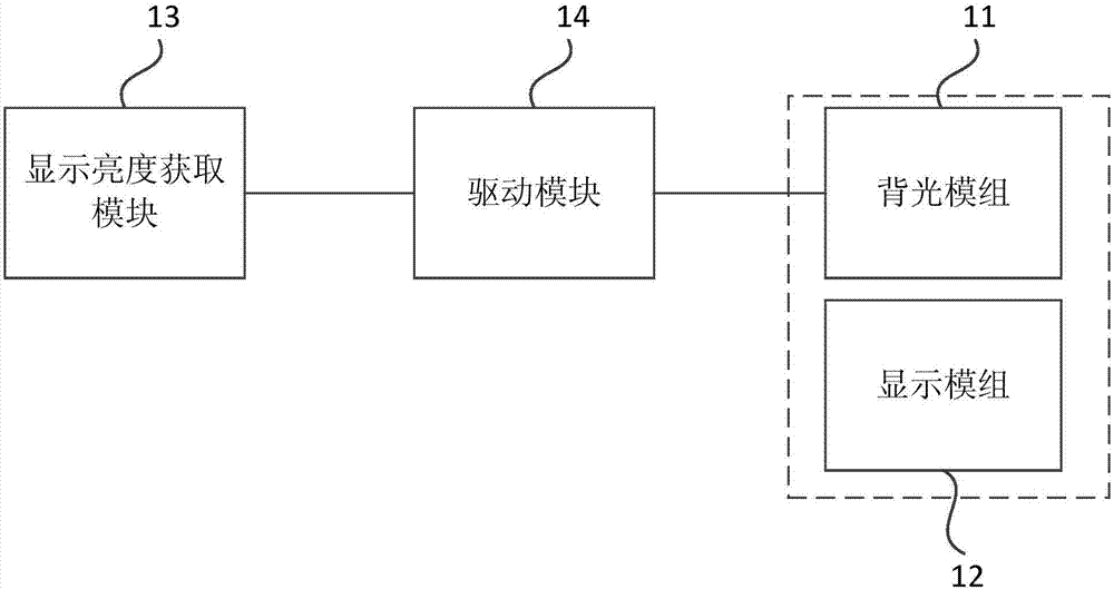
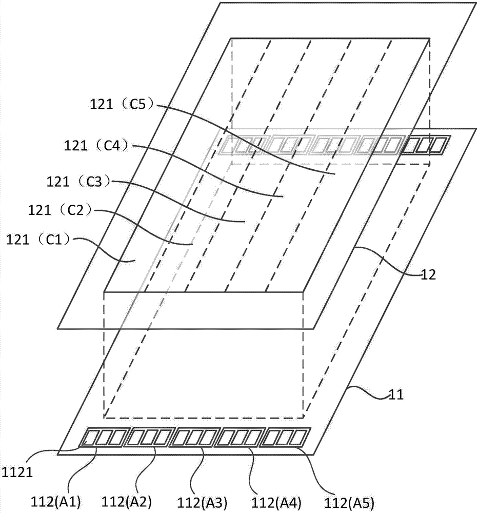
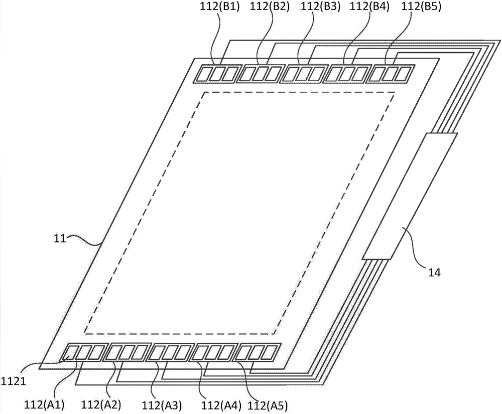
[0039] figure 1 It is a structural block diagram of a display device provided by Embodiment 1 of the present invention. figure 2 It is a schematic structural diagram of a backlight module and a display module in a display device provided in Embodiment 1 of the present invention. image 3 for figure 2 Schematic diagram of the structure of the backlight module in . see figure 1 , figure 2 and image 3 , the display device includes a backlight module 11 , a display module 12 opposite to the backlight module 11 , a display brightness acquisition module 13 and a driving module 14 . The backlight module 11 includes a plurality of light source groups 112 , and each light source group 112 includes at least one light emitting unit 1121 , and each light emitting unit 1121 in the same light source group 112 is electrically connected to the same port of the driving module 14 . The display module 12 includes a plurality of sub-display areas 121 , and each sub-display area 121 corr...
Embodiment 2
[0050] Figure 4 A schematic structural diagram of a backlight module in a display device provided by Embodiment 2 of the present invention. Figure 5 for along Figure 4 Sectional view of D1-D2 in the middle. Figure 4 and Figure 5 The backlight module provided in is an edge-lit backlight module. This embodiment is a specific example of the first embodiment.
[0051] see Figure 4 and Figure 5 , the backlight module 11 also includes a light guide plate 15; the light guide plate 15 includes at least one light incident surface 151, a light reflective surface 152 intersecting the light incident surface 151, and a light exit surface 153, the light reflective surface 152 and the light exit surface 153 are arranged oppositely, and the light guide plate A plurality of light source groups 112 are provided on any side of the light incident surface 151 of the light guide plate 15 ; In use, after the light emitted by the light source group 112 enters the light guide plate 15 , ...
Embodiment 3
[0055] Figure 7 A schematic structural diagram of a backlight module in a display device provided by Embodiment 3 of the present invention. Figure 8 for along Figure 7 Sectional view of E1-E2 in Fig. Figure 7 and Figure 8 The backlight module provided in is an edge-lit backlight module. This embodiment is a specific example of the second embodiment.
[0056] see Figure 7 and Figure 8 , the backlight module 11 further includes a light guide plate 15 . The light guide plate 15 is a microstructure light guide plate. Exemplarily, the light guide plate 15 includes two light incident surfaces 151, a light reflective surface 152 intersecting the light incident surfaces 151, and a light exit surface 153, the two light incident surfaces 151 are arranged oppositely, and the light reflective surface 152 and the light exit surface 153 are oppositely arranged; The light emitting surface 153 includes a plurality of strip-shaped protrusions 155 , and the extending direction of...
PUM
 Abstract
Description
Claims
Application Information
 - R&D
- Intellectual Property
- Life Sciences
- Materials
- Tech Scout
- Unparalleled Data Quality
- Higher Quality Content
- 60% Fewer Hallucinations
Browse by: Latest US Patents, China's latest patents, Technical Efficacy Thesaurus, Application Domain, Technology Topic, Popular Technical Reports.
© 2025 PatSnap. All rights reserved.Legal|Privacy policy|Modern Slavery Act Transparency Statement|Sitemap|About US| Contact US: help@patsnap.com