Atomization components and electronic cigarettes

An atomization component and electronic cigarette technology, which is applied in the field of electronic cigarettes, can solve problems such as damage to the control circuit board, offset of the heating wire, damage to the electronic cigarette, etc., and achieve the effects of avoiding short circuit, avoiding burning, and increasing stability

Active Publication Date: 2020-01-10
KIMSUN TECHHUIZHOU CO LTD
View PDF5 Cites 0 Cited by
  • Summary
  • Abstract
  • Description
  • Claims
  • Application Information

AI Technical Summary

Problems solved by technology

[0003] However, the heating wire wound on the oil guide is prone to deflection when it is subjected to impact or placed on an incline for a long time, so that the heating wire may come into contact with the inner cavity of the atomizing seat, which will cause a short circuit in the entire circuit and damage the control circuit board
This defect in the existing technology makes the electronic cigarette vulnerable to damage when it is hit or slipped, and the user experience is poor

Method used


Image

  • Atomization components and electronic cigarettes
  • Atomization components and electronic cigarettes
  • Atomization components and electronic cigarettes

Examples


Embodiment 1

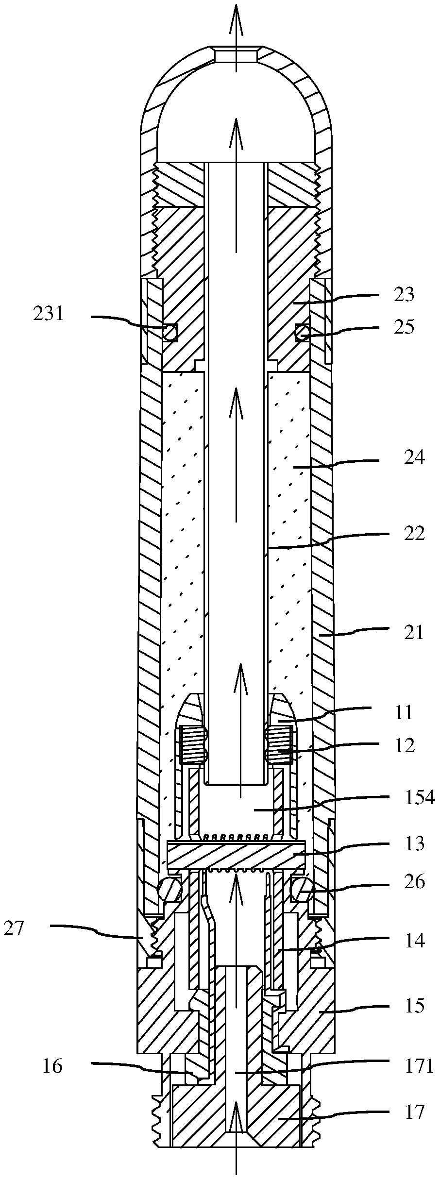
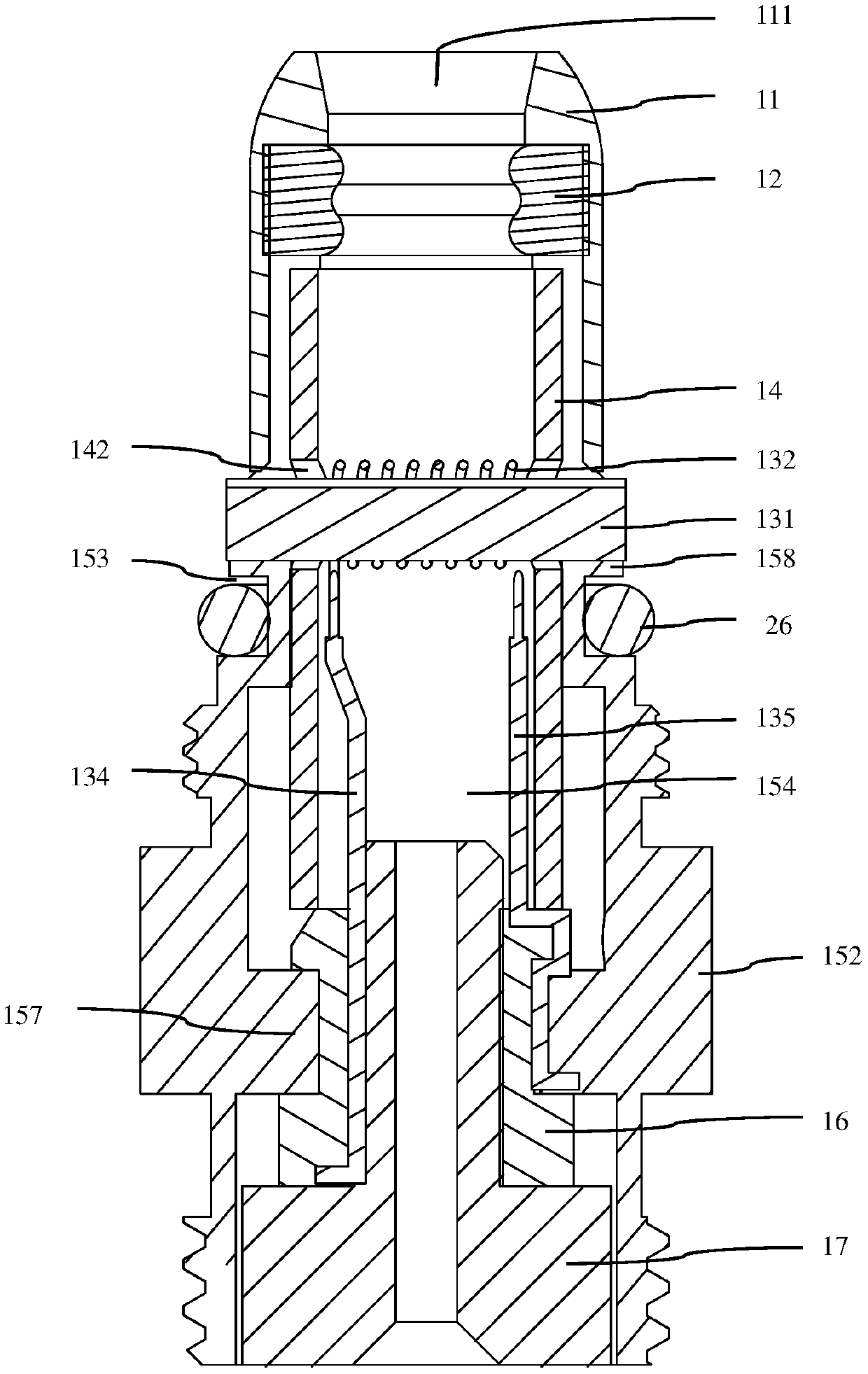
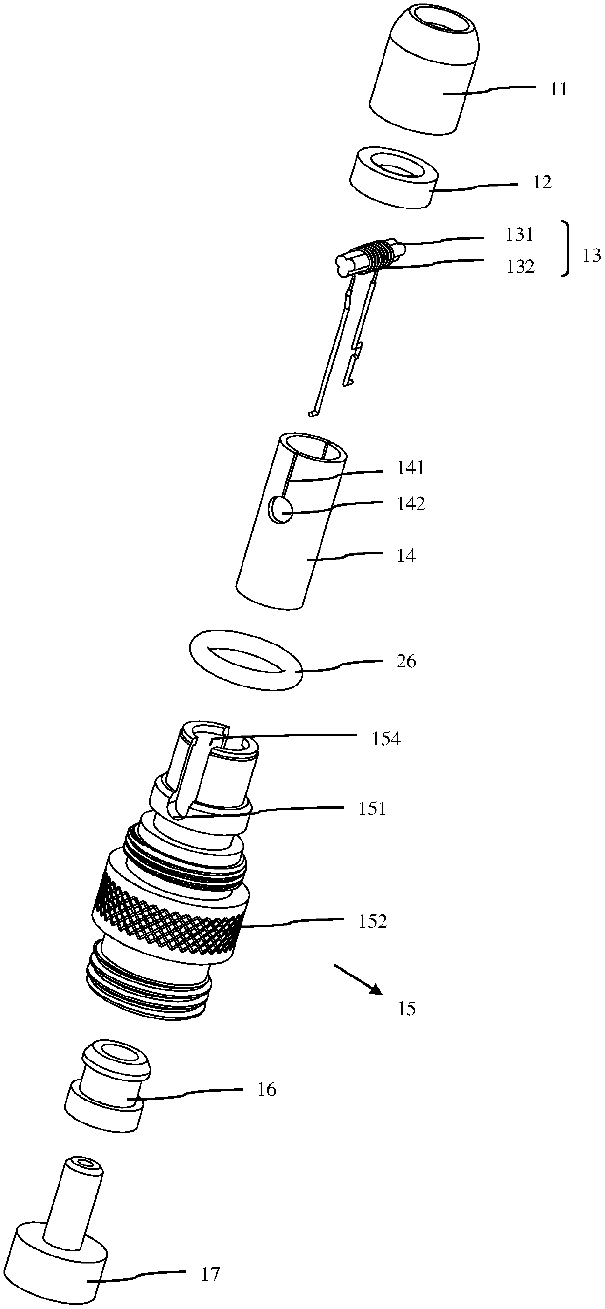
[0040] Example 1: Please refer to figure 1 , figure 2 , image 3 and Figure 4 .

[0041] The atomization assembly provided by the present invention includes an oil cup assembly and an atomization core arranged in the oil cup assembly, wherein the oil cup assembly includes an atomization sleeve 21, a vent pipe 22, an oil separator 23 and a suction nozzle assembly, and The atomizing core, the atomizing sleeve 21 , the air pipe 22 and the oil separator 23 form an oil storage chamber 24 for storing e-liquid.

[0042]The atomizing sleeve 21 is a hollow tubular structure, one end of which is detachably connected to the atomizing core through a connecting piece 27, and the other end is detachably connected to the oil separator 23 and the nozzle assembly respectively. In this embodiment, the oil separator 23 is inserted into the port of the atomizing sleeve 21 to prevent the liquid from leaking out, and the suction nozzle assembly is sleeved outside the atomizing sleeve 21 and i...

Embodiment 2

[0066] Example 2: Please refer to Figure 5 , and combined with figure 1 , figure 2 and image 3 .

[0067] The difference between this embodiment and the first embodiment is that the insulating tube 14 is arranged coaxially with the inner cavity of the atomizing seat 15, the cutout 141 extends from the fixing hole 142 to the outer wall surface of the insulating tube 14, and the direction of the cutout 141 is the same as that of the insulating tube The axes of 14 are vertical, that is, the cutout 141 is arranged horizontally.

Embodiment 3

[0068] Example 3: Please refer to Figure 6 , and combined with figure 1 , figure 2 and image 3 .

[0069] The difference between this embodiment and the previous embodiments is that the insulating tube 14 is arranged coaxially with the inner chamber of the atomizing seat 15, the cutout 141 extends from the fixing hole 142 to the side wall of the insulating tube 14, and the direction of the cutout 141 is consistent with the insulation The axial directions of the tubes 14 intersect, that is, the cutouts 141 are arranged obliquely.


PUM


Abstract

An atomization assembly and an electronic cigarette, wherein the atomization assembly includes an oil cup assembly and an atomization core arranged in the oil cup assembly, the oil cup assembly has an oil storage cavity (24) for containing smoke oil; the atomization core Comprising an atomization seat (15) and a heating wire assembly (13), the atomization seat (15) is provided with a smoke channel (154) for the circulation of the smoke obtained by atomization, and the heating wire assembly (13) is arranged in the smoke channel ( 154), the heating wire assembly (13) includes a heating wire (132) for heating atomized e-liquid; the atomization core also includes a heating wire (132) for isolating the atomization seat (15) and the heating wire (132) The insulating tube (14), the insulating tube (14) is inserted in the atomizing seat (15), and supports the heating wire assembly (13) along the longitudinal direction of the atomizing seat (15). The atomization component and the electronic cigarette have the advantages of avoiding short circuit, strong impact resistance, and not easy to be damaged.

Description

technical field [0001] The present invention relates to the technical field of electronic cigarettes, and more specifically, relates to an atomizing component and electronic cigarettes. Background technique [0002] An existing electronic cigarette includes an atomizing assembly and a battery assembly, and the atomizing assembly includes an atomizing sleeve for storing e-liquid and an atomizing core inserted into one end of the atomizing sleeve. Wherein, the atomizing core is provided with an atomizing seat made of metal material, an inner electrode inserted at one end of the atomizing seat, and a heating wire assembly for atomizing the e-liquid in the atomizing sleeve. The heating wire assembly is generally inserted laterally in the central area of ​​the atomizing seat, and the inner electrode and one end of the atomizing seat are usually used as electrodes to conduct electric energy to the heating wire in the heating wire assembly. [0003] However, the heating wire wound...

Claims


Application Information

Patent Timeline
Patent Type & Authority Patents(China)
IPC IPC(8): A24F47/00A24F40/10A24F40/40
CPCH05B2203/014H05B2203/021H05B2203/022H05B3/44A24F40/10A24F40/40F22B1/284
Inventor 刘秋明
Owner KIMSUN TECHHUIZHOU CO LTD
Why Eureka
Try Eureka