slider for zipper

A slider and zipper technology, applied in applications, apparel, sliding fastener elements, etc., can solve problems such as reduced availability of zippers, and achieve the effect of ease of use

Active Publication Date: 2019-11-08
YKK CORP
View PDF7 Cites 0 Cited by
  • Summary
  • Abstract
  • Description
  • Claims
  • Application Information

AI Technical Summary

Problems solved by technology

[0003] Even if the pull-tab mounting post is plastically deformed as in the above example, a small gap remains, and foreign objects such as bags may be caught in the gap, reducing the usability of the zipper

Method used


Image

  • slider for zipper
  • slider for zipper
  • slider for zipper

Examples


no. 1 Embodiment approach

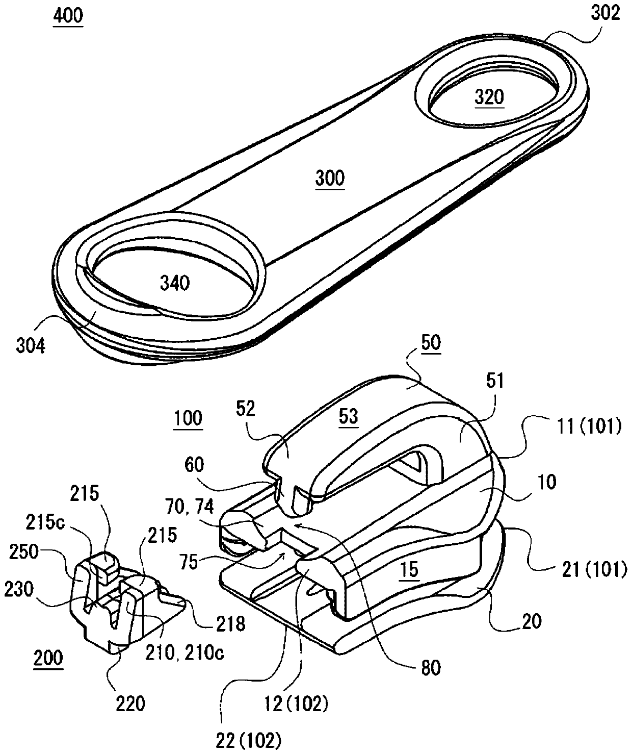
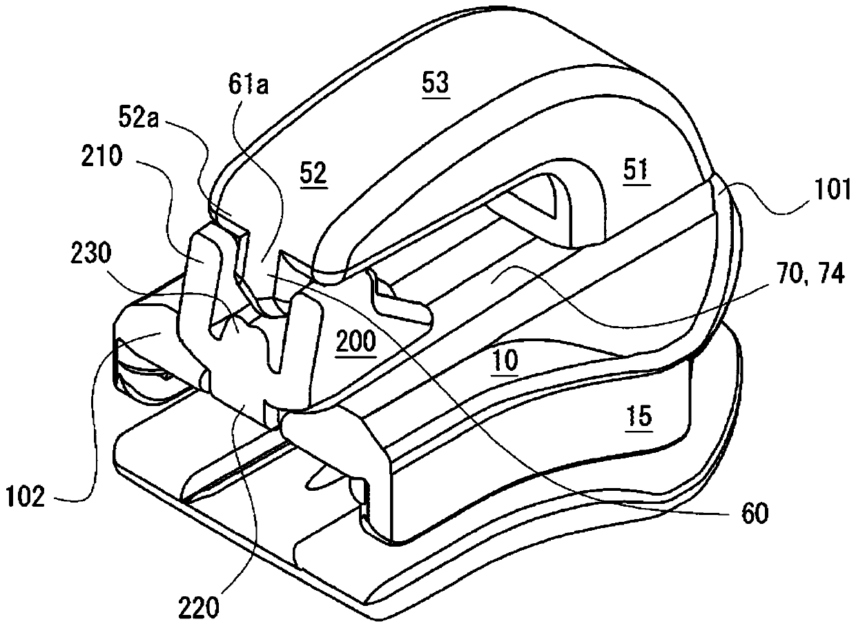
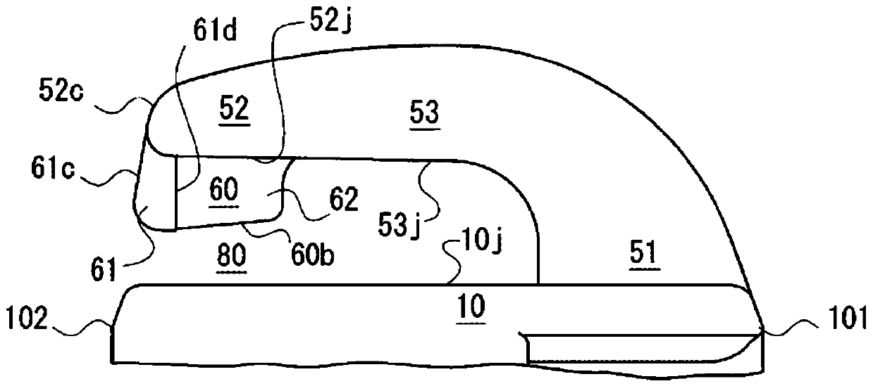
[0040] refer to Figure 1 to Figure 10 The first embodiment will be described. figure 1 It is a schematic exploded perspective view of a slider with a pull tab. figure 2 It is a schematic perspective view of a slider with a pull tab, and the illustration of the pull tab is omitted for convenience of illustration. image 3 is a schematic partial side view of the slider body of a slider with a pull tab, particularly showing the sides of the upper wing and the tab mounting post. Figure 4 It is a schematic partial cross-sectional schematic diagram of the slider main body of the slider with a pull tab, and particularly shows the cross-section of the upper wing plate and the tab mounting column. Figure 5It is a schematic diagram which compared the rough partial side view of the slider main body of the slider with a slider, and the partial cross-sectional schematic diagram. Figure 6 It is a back view of the closure member of the slider with a pull tab, and the pivoting form of...


PUM


Abstract

 A slider (400) for a slide fastener is provided with a slider body (100) and a blocking member (200). The upper wing plate (10) of the slider body (100) is provided with a recessed placement part (70) on which the blocking member (200) is placed, and a fitting hole (75) into which the fitting projection (220) of the blocking member (200) is inserted and fitted is provided to the placement part (70) in such a way that the end of the upper wing plate (10) is cut out. The placement part (70) and the fitting hole (75) extend along the direction in which the blocking member (200) is moved in order for the blocking member (200) to be mounted in the slider body (100). The length of the fitting hole (75) in the direction of movement is less than the length of the placement part (70) in the direction of movement.

Description

technical field [0001] The present invention relates to sliders for slide fasteners. Background technique [0002] The technique of retrofitting a handle to a slider body having a cantilever-shaped handle attachment column is known. To allow rear mounting of the tab, there is a gap between the free end of the tab mounting post and the upper wing of the slider body. This clearance is required when the tab is installed post-installation, but is no longer required after the tab is installed. Therefore, in a certain method, after attaching a handle, it plastically deforms a handle attachment column, and reduces this clearance gap. However, in this case, it may be required to suppress undesired deformation of the slider body due to force applied to the handle mounting post, for example, variation in the interval between the upper blade and the lower blade. [0003] Even if the handle attachment column is plastically deformed like the above-mentioned example, a minute gap remai...

Claims


Application Information

Patent Timeline
Patent Type & Authority Patents(China)
IPC IPC(8): A44B19/26
CPCA44B19/26
Inventor 本田真也
Owner YKK CORP
Why Eureka
Try Eureka