Magnetic element and flat panel display device comprising same

A technology of magnetic components and substrates, applied in the direction of printed circuits, electrical components, magnetic cores/yokes, etc. connected to non-printed electrical components, can solve the problem of reducing magnetic components and achieve the effect of ensuring ease

Pending Publication Date: 2022-01-18
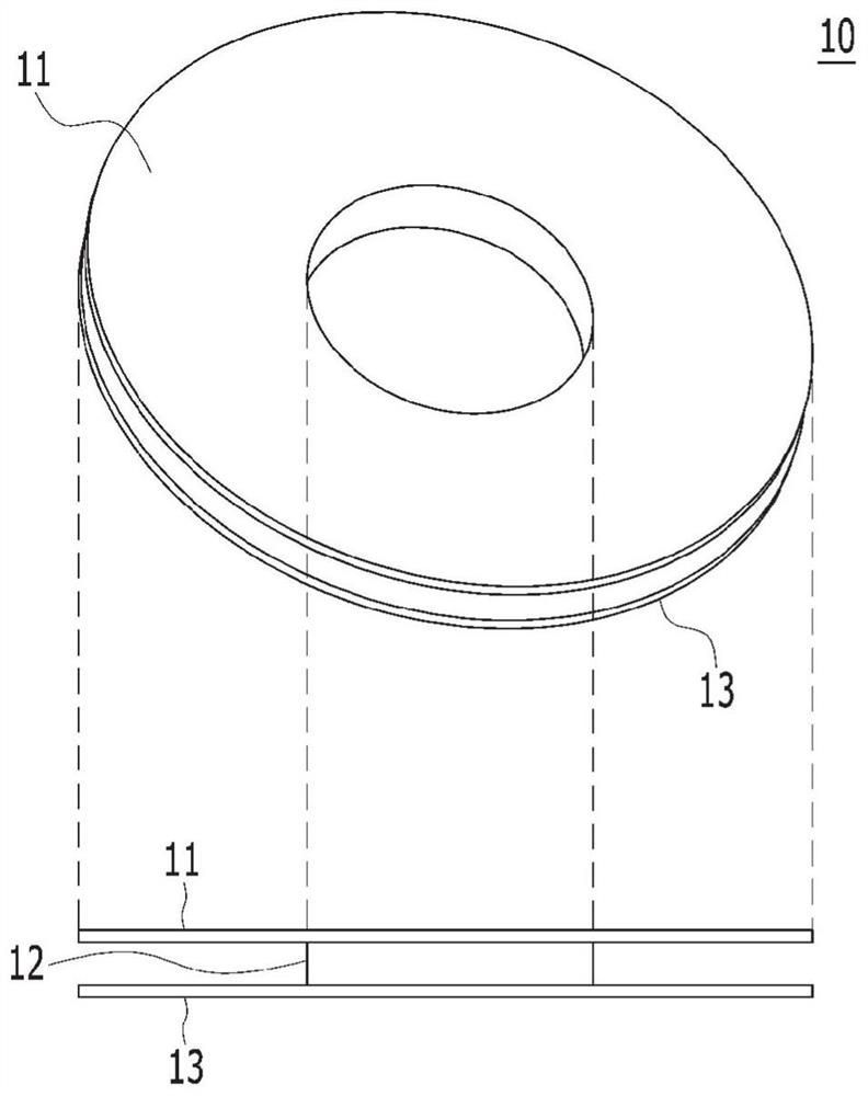
LG INNOTEK CO LTD
View PDF0 Cites 0 Cited by
  • Summary
  • Abstract
  • Description
  • Claims
  • Application Information

AI Technical Summary

Problems solved by technology

As a result, when a typical bobbin is applied, there is a limit to further reducing the height h4 of the magnetic element protruding from the upper surface of the substrate 40

Method used


Image

  • Magnetic element and flat panel display device comprising same
  • Magnetic element and flat panel display device comprising same
  • Magnetic element and flat panel display device comprising same

Examples


Embodiment Construction

[0040] Reference will now be made in detail to the various embodiments of the invention, specific examples of which are illustrated in the drawings and described below, since the embodiments of the invention can be variously modified in many different forms. While the invention will be described in conjunction with exemplary embodiments thereof, it will be understood that present description is not intended to limit the invention to those exemplary embodiments. On the contrary, the invention is intended to cover not only the exemplary embodiments, but also various alternatives, modifications, equivalents and other embodiments, which may be included within the spirit and scope of the invention as defined by the appended claims .

[0041]It should be understood that although the terms "first", "second", etc. may be used herein to describe various elements, these elements should not be limited by these terms. These terms are generally only used to distinguish one element from an...


PUM


Abstract

An inductor according to one embodiment of the present invention comprises: a core part; a coil part having one or more coils which are wound around the midfoot of the core part and which have two ends; and a base which is arranged beneath the coil part and which supports at least a part of the outer circumferential surface of each of the one or more coils, wherein the base can comprise: a frame having a hollow hole, which is formed at the center thereof so as to include a longer shaft and a shorter shaft; and a support part having a plurality of support members protruding toward the outer circumferential surface, so as to encompass at least a part of the outer circumferential surface.

Description

technical field [0001] Embodiments relate to a magnetic element and a circuit board and flat panel display device including the same. Background technique [0002] Usually, driving an electronic device requires driving power, and essentially a power supply (for example, a power module) is used to provide driving power for the electronic device. According to the thinning trend of electronic equipment in recent years, the thinning of passive magnetic elements constituting a power supply, such as inductors, is also necessary. [0003] However, when the coil is formed from wire, a bobbin is usually applied to such passive magnetic elements to maintain the shape of the coil and facilitate winding. will refer to Figure 1 to Figure 2b Describe a typical skeleton. [0004] figure 1 A typical skeleton is shown. [0005] refer to figure 1 , a perspective view of the frame 10 is shown on the upper side of the figure, and a side view of the frame 10 is shown on the lower side of...

Claims


Application Information

Patent Timeline
Patent Type & Authority Applications(China)
IPC IPC(8): H01F27/24H01F27/28H01F27/30H05K1/18
CPCH01F27/24H01F27/28H01F27/30H01F27/306H05K1/18H01F17/04G09F9/37H01F27/06H01F2027/065H01F27/325H01F3/00G09F9/375H01F27/266H01F27/2823
Inventor 南泽薰金宥宣裵硕
Owner LG INNOTEK CO LTD
Why Eureka
Try Eureka