Multilayer channel member and ultrasonic fluid measuring device using same

A technology of flow path components and fluid meters, which is applied in the direction of measuring devices, liquid/fluid solid measurement, flow measurement/mass flow, etc., can solve the problems of measurement accuracy reduction, cost increase, size deviation, etc., and improve the side plate Effects of strength, improvement of measurement accuracy, and simple configuration

Inactive Publication Date: 2011-08-03
PANASONIC CORP
View PDF7 Cites 1 Cited by
  • Summary
  • Abstract
  • Description
  • Claims
  • Application Information

AI Technical Summary

Problems solved by technology

[0023] However, when forming the flow channel for measurement as a multilayer flow channel, there are problems as follows: due to the positional relationship between the pair of ultrasonic transducers and the multilayer flow channel installed in the flow channel for measurement and the use of support for forming In the case of the two edges of the rectifying plate of the multi-layer flow channel, the dimensional deviation between the rectifying plates has the problem of reducing the measurement accuracy. In order to perform high-precision measurement, high-precision multi-layer flow channel components are required.
[0024] In addition, in the former example of using the flow channel for measurement as a multi-layer flow channel, a plurality of rectifying plates and the support parts supporting them are integrally insert-molded using thermosetting resin, which requires time for hardening It takes a very long time to take out the molded product from the molding die after injecting the resin into the molding die, which leads to poor productivity and a corresponding increase in cost.
[0025] Therefore, if a thermoplastic resin is used instead of a thermosetting resin, the shrinkage will be la

Method used


Image

  • Multilayer channel member and ultrasonic fluid measuring device using same
  • Multilayer channel member and ultrasonic fluid measuring device using same
  • Multilayer channel member and ultrasonic fluid measuring device using same

Examples


Embodiment approach 1

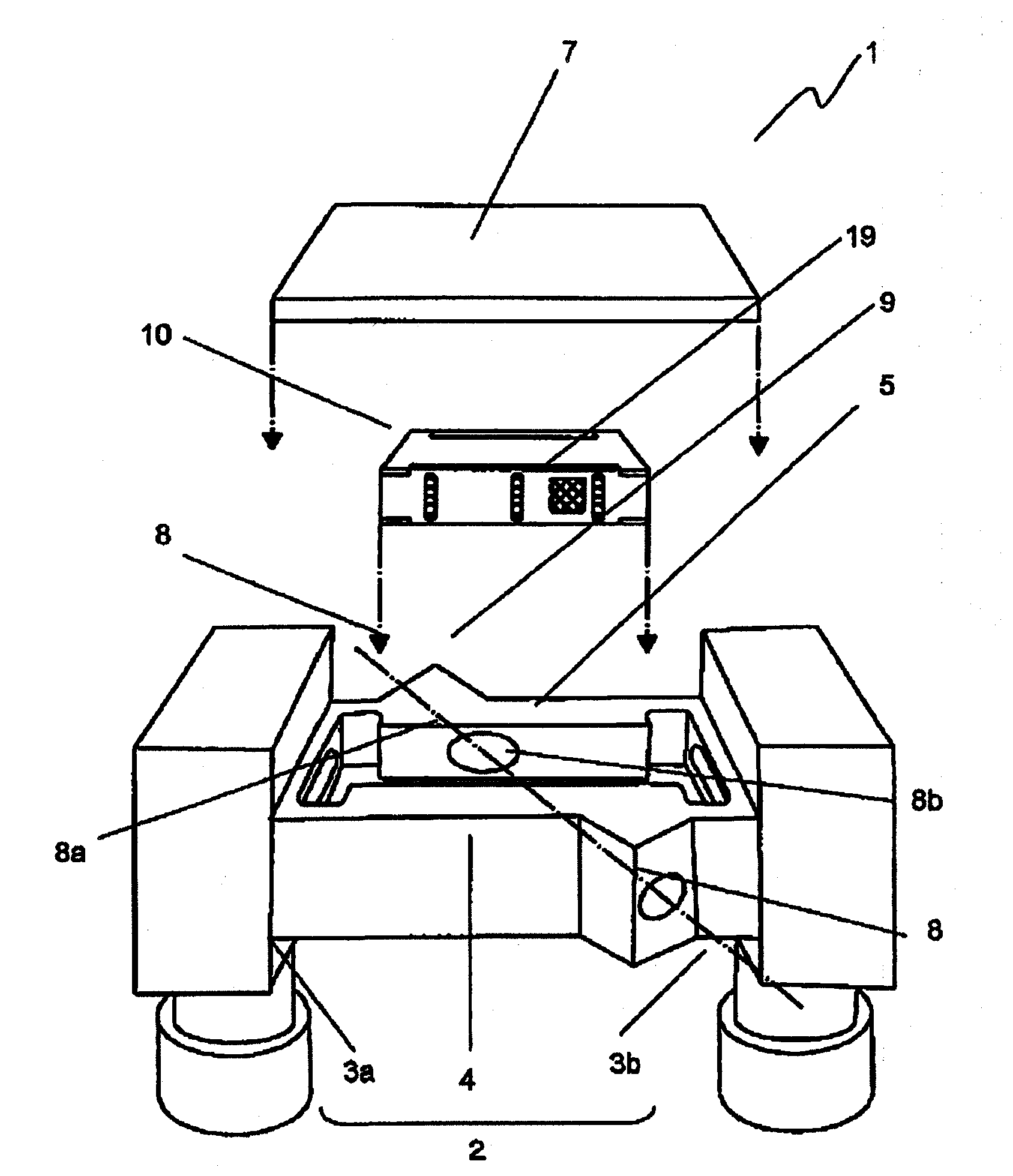
[0076] exist Figure 1~4 Among them, the fluid channel 2 of the ultrasonic fluid measuring device 1 is formed in a substantially inverted U-shape by left and right vertical channels 3a, 3b and a horizontal channel 4 connecting the upper ends of the left and right vertical channels 3a, 3b.

[0077] The horizontal flow path 4 has a square tube-shaped measurement flow path housing portion 5 with an upper opening for measuring fluid, and the measurement flow path housing portion 5 is provided with two transmitting and receiving wave channels in a pair-to-pair manner. The ultrasonic measurement unit 9 having a transmitter and receiver (not shown) is provided on the instrument mounting unit 8, respectively.

[0078] In addition, the measurement channel housing part 5 has a multilayer channel member 10 that divides the fluid into a plurality of flat channels, and a cover part 7 that houses the multilayer channel member 10 in the measurement channel housing part 5 and seals it. .

...

Embodiment approach 2

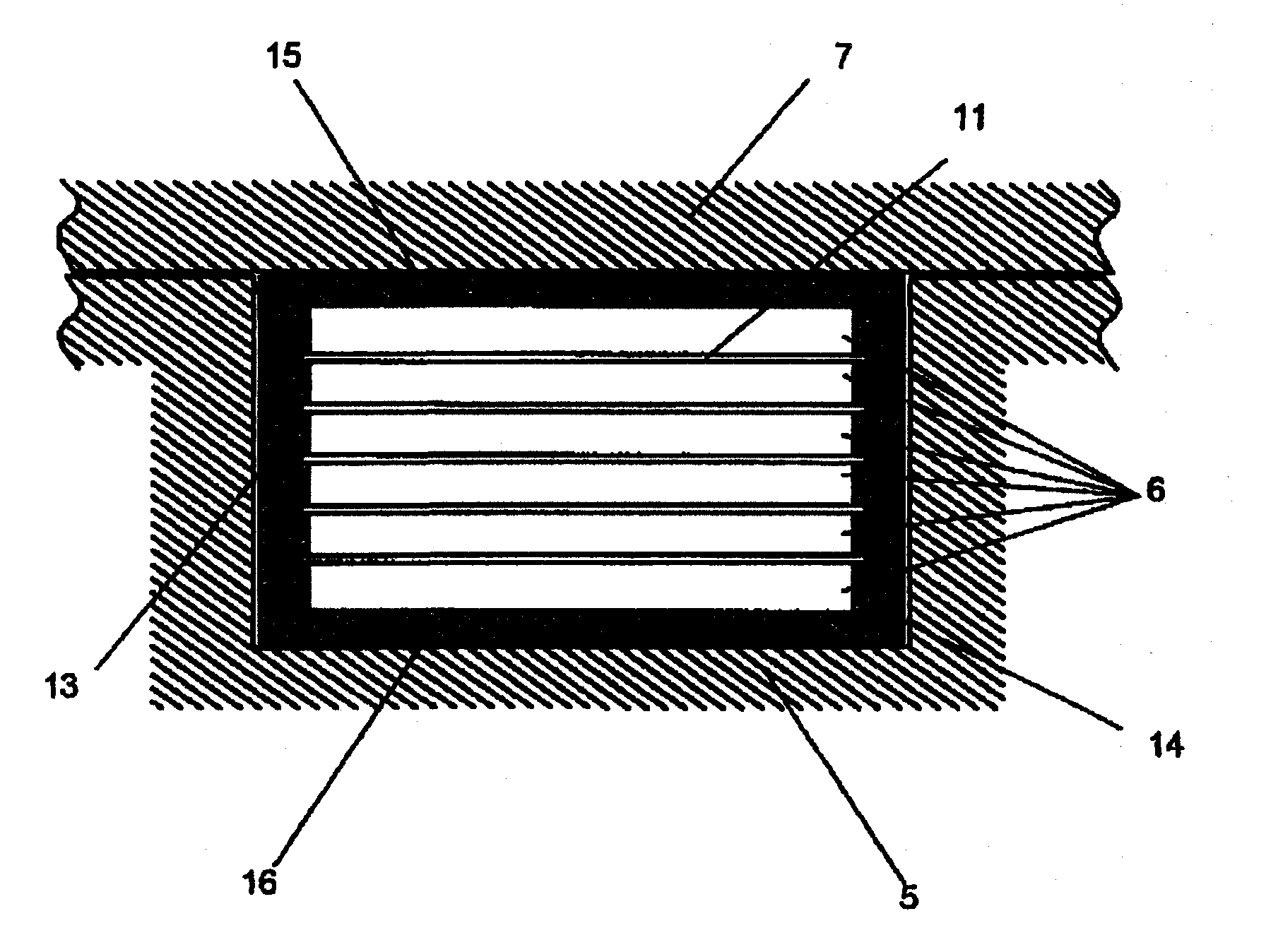
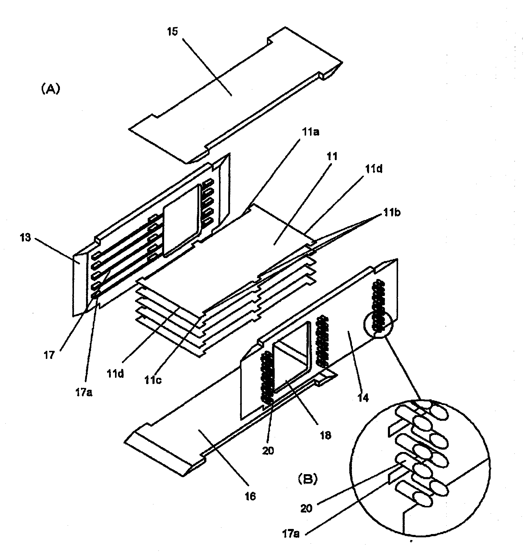
[0097] Figure 5-7 shows Embodiment 2 of the present invention, and has image 3 , 4 Components with the same function are assigned the same reference numerals, and the content of Embodiment 1 is referred to for the specific description.

[0098] like Figure 5 , Image 6 As shown, the melting protrusions 25 provided above and below the insertion hole 17a into which a part of the separator 11 is inserted have the welding surface at the front end portion inclined in the vertical direction, and the shape is changed, that is, the height is changed, and the separator 11 is changed. The amount of fusion of the melting protrusions 25 provided above and below the insertion holes 17a, 17a of the side plates 13, 14 differs on the upper and lower sides of the partition 11, and the gap between the insertion holes 17a and the partition 11 is formed in a certain direction.

[0099] Alternatively, assemble as Figure 7 As shown, a positioning jig 30 having slits 32 set to space the par...

Embodiment approach 3

[0117] like Figure 9 As shown, the fluid channel 202 of the ultrasonic fluid measuring device 201 is formed in a substantially inverted U-shape by the left and right vertical channels 203a, 203b, and the horizontal channel 204 connecting the upper ends of the left and right vertical channels 203a, 203b. .

[0118] The horizontal flow path 204 has a measurement flow path housing portion 205 with a rectangular cross-section and an open upper surface, and a transmitter / receiver mounting portion 206 is formed on the opposite short side wall portion thereof, constituting an ultrasonic measurement portion 207 .

[0119] Furthermore, a multilayer flow path member 208 that divides the fluid into a plurality of flat flow paths is accommodated in the measurement flow path housing portion 205 , and the upper open portion is sealed with a lid portion 209 .

[0120] A circular through-hole 206a is formed in the transmitter-receiver mounting portion 206 of the short side wall portion of t...


PUM


Abstract

Provided are a multilayer channel member enabling improvement of the accuracy of measurement of a fluid by an ultrasonic fluid measuring device and an ultrasonic fluid measuring device using the same. Fusion projections (20) are fused by a heating head (21) while partition plates (11) are inserted between side plates (13, 14). Since the welding surfaces of the tip portions of the fusion projections (20) are inclined vertically, the states of fusion of the upper and bottom surfaces of each partition plate (11) by the heating head (21) are different. The tip portion of each fusion projection (25) first brought into contact with the heating head (21) is fused first, and the fusion progresses to the root portion of the fusion projection (25). During the fusion, the partition plates (11) are pressed against the edges of insertion holes (17a) opposite to the tip portions fused first, biased with respect to the insertion holes (17a), secured with the position accuracy by the insertion holes (17a), and thus can be welded accurately even if there is a gap between a partition plate (11) and the insertion hole (17a).

Description

technical field [0001] The present invention relates to a multilayer flow path member having a measurement flow path composed of a plurality of flat flow paths and an ultrasonic fluid measurement device using the same. Background technique [0002] The ultrasonic fluid measuring device is a device that flows a fluid through a measurement channel, propagates ultrasonic waves in the measurement channel, measures the propagation time of the ultrasonic waves, and obtains the fluid flow velocity based on the measured information. [0003] Furthermore, the flow path for measurement has a rectangular shape with a rectangular cross section, and a pair of ultrasonic transceivers are provided on opposite short sides. [0004] The pair of ultrasonic transceivers are arranged so as to form an ultrasonic propagation path at a predetermined angle with respect to the flow direction of the measurement flow path, that is, obliquely crossing the fluid flow direction. [0005] Furthermore, in...

Claims


Application Information

Patent Timeline
IPC IPC(8): G01F1/66G01F1/00
CPCG01F1/662G01F15/14G01F15/00
Inventor 后藤寻一重冈武彦
Owner PANASONIC CORP
Why Eureka
Try Eureka