
Valve, fluid control device, and blood pressure meter

A valve housing and valve seat technology, which can be applied to valve devices, components of pumping devices for elastic fluids, control valves, etc., and can solve problems such as pressure errors.

Active Publication Date: 2017-08-18
MURATA MFG CO LTD
View PDF7 Cites 5 Cited by
  • Summary
  • Abstract
  • Description
  • Claims
  • Application Information

AI Technical Summary

Problems solved by technology

[0028] Therefore, in the valve 901 of Patent Document 1, when blood pressure is measured next time, an error occurs in the amount of pressure remaining in the cuff 109

Method used


Image

  • Valve, fluid control device, and blood pressure meter
  • Valve, fluid control device, and blood pressure meter
  • Valve, fluid control device, and blood pressure meter

Examples


other Embodiment approach

[0205] In addition, in the above-mentioned embodiment, air is used as the fluid, but the present invention is not limited to this, and the fluid can be applied even if it is a gas other than air.

[0206] In addition, in the above-mentioned embodiment, the blood pressure monitor device was shown as an example of the fluid control device, but it is not limited thereto. Gas may be filled into a container other than a cuff in a fluid control device other than a sphygmomanometer device.

[0207] In addition, the pump in the above-described embodiment includes the actuator 40 that flexibly vibrates in the single crystal type, but it may also include an actuator that vibrates in the bimorph flexurally by attaching piezoelectric elements to both surfaces of the vibration plate.

[0208] In addition, although the sphygmomanometer device in the above-mentioned embodiment includes the piezoelectric pump 10 driven by expansion and contraction of the piezoelectric element 42, the present ...


PUM


Abstract

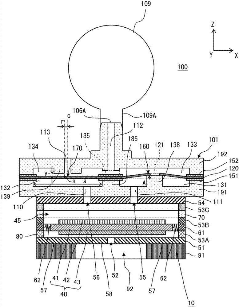
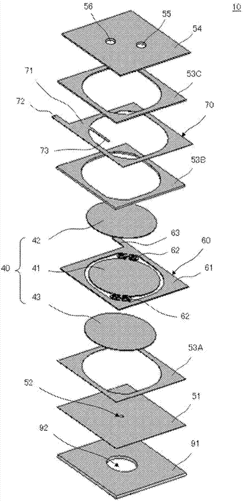
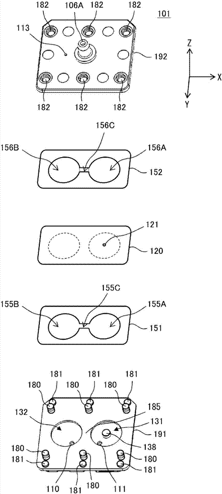
A blood pressure meter device (100) is equipped with a piezoelectric pump (10), a valve (101), and a cuff (109). The valve (101) is equipped with a first valve housing (191), a diaphragm (120), and a second valve housing (192). The diaphragm (120) is secured to the second valve housing (192) and the first valve housing (191) so that the diaphragm (120) is separated from a valve seat (139) and the periphery of an opening section (121) in the diaphragm (120) is in contact with and applies pressure to the valve seat (138). Because of this configuration, the diaphragm (120), along with the second valve housing (192) and the first valve housing (191), constitutes a lower valve chamber (131) that is in communication with a first air hole (111), an upper valve chamber (133) that is in communication with a second air hole (112), a lower valve chamber (132) that is in communication with a first air hole (110), and an upper valve chamber (134) that is in communication with the upper valve chamber (133).

Description

technical field [0001] The present invention relates to a valve for preventing fluid backflow, a fluid control device including the valve, and a sphygmomanometer including the fluid control device. Background technique [0002] Patent Document 1 discloses a fluid control device including a valve. [0003] Figure 17 It is a sectional view of main parts of the fluid control device 900 of patent document 1. The fluid control device 900 includes a piezoelectric pump 10 , a valve 901 , and a cuff (Cuff) 109 . [0004] The fluid control device 900 is a device that measures the blood pressure of a subject. The valve 901 is connected to the piezoelectric pump 10 by bonding the upper surface of the piezoelectric pump 10 to the bottom surface of the valve 901 . Furthermore, a cuff 109 is connected to the cuff connection port 106A of the valve 901 . The cuff 109 is a flexible container capable of storing air. Details of the piezoelectric pump 10 will be described later. [0005]...

Claims


Application Information

Patent Timeline
IPC IPC(8): A61B5/0235F04B43/04F16K7/17F16K15/14
CPCA61B5/0235A61M39/24A61M2039/2406A61M2039/2413A61M2039/2493F04B45/047F04B53/06F04B53/1087F16K15/144F04B53/106F16K7/17
Inventor 川村宪一郎
Owner MURATA MFG CO LTD
Learn More