
Monitoring apparatus for monitoring blood pressure of a subject

a monitoring apparatus and blood pressure technology, applied in the field of monitoring apparatus for monitoring vital sign information of a subject, can solve the problems of increasing the risk of infection, obstructing and uncomfortable for users, and non-invasive blood pressure measurement systems require a large technical effort, and achieve the effect of reliable measurement of blood pressur

Active Publication Date: 2018-08-23
KONINKLJIJKE PHILIPS NV
View PDF5 Cites 29 Cited by
  • Summary
  • Abstract
  • Description
  • Claims
  • Application Information

AI Technical Summary

Benefits of technology

The present invention is about an improved device and method for measuring blood pressure. The device helps to monitor the blood pressure of a person in a comfortable way. The technical effects of the invention are that it provides accurate blood pressure readings and is user-friendly.

Problems solved by technology

Common measurement methods are performed either discontinuously by means of a cuff, which is cumbersome and uncomfortable for the user or continuously by means of an arterial line, which is invasive and increases the risk of an infection.
The known blood pressure measurement systems which monitor the blood pressure by determining the pulse arrival time utilize a plurality of electrocardiographic electrodes disposed on the chest and a photoplethysmography sensor at a finger, which require cable connections in order to evaluate the respective measurement signals, so that the known non-invasive blood pressure measurement systems require a large technical effort, are obstructive and uncomfortable for the user.
Further, since the photoplethysmography sensor is disposed at a finger and the peripheral vascular resistance of the arms vary due to factors which are not related to the blood pressure, the measurement results have a reduced reliability.

Method used


Image

  • Monitoring apparatus for monitoring blood pressure of a subject
  • Monitoring apparatus for monitoring blood pressure of a subject
  • Monitoring apparatus for monitoring blood pressure of a subject

Examples


Embodiment Construction

[0064]Certain embodiments will now be described in greater details with reference to the accompanying drawings. In the following description, like drawing reference numerals are used for like elements, even in different drawings. The matters defined in the description, such as detailed construction and elements, are provided to assist in a comprehensive understanding of the exemplary embodiments. Also, well-known functions or constructions are not described in detail since they would obscure the embodiments with unnecessary detail. Moreover, expressions such as “at least one of”, when preceding a list of elements, modify the entire list of elements and do not modify the individual elements of the list.

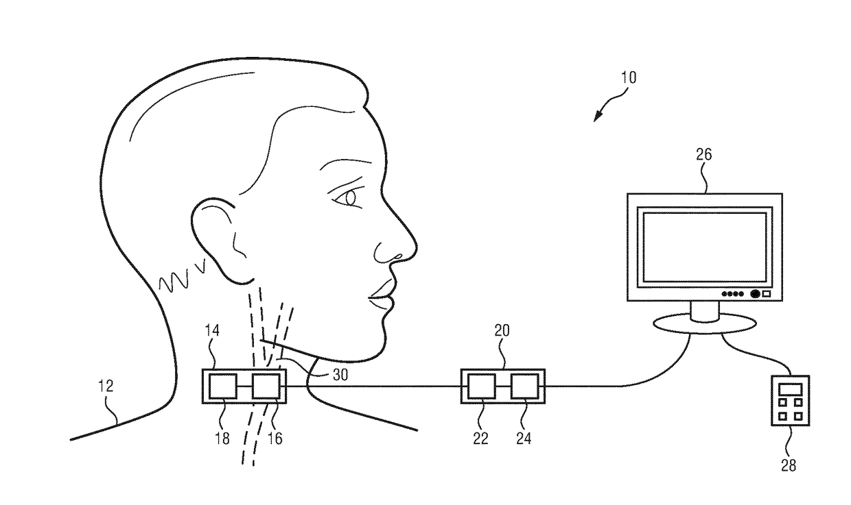
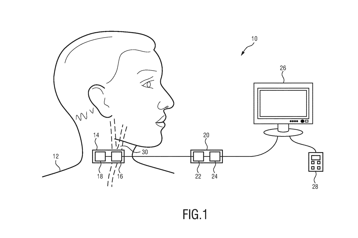
[0065]FIG. 1 shows a schematic illustration of a monitoring apparatus generally denoted by 10. The monitoring apparatus 10 is provided for monitoring vital sign information of a subject 12, in particular a patient 12. The monitoring apparatus comprises a measurement unit 14 having an u...


PUM


Abstract

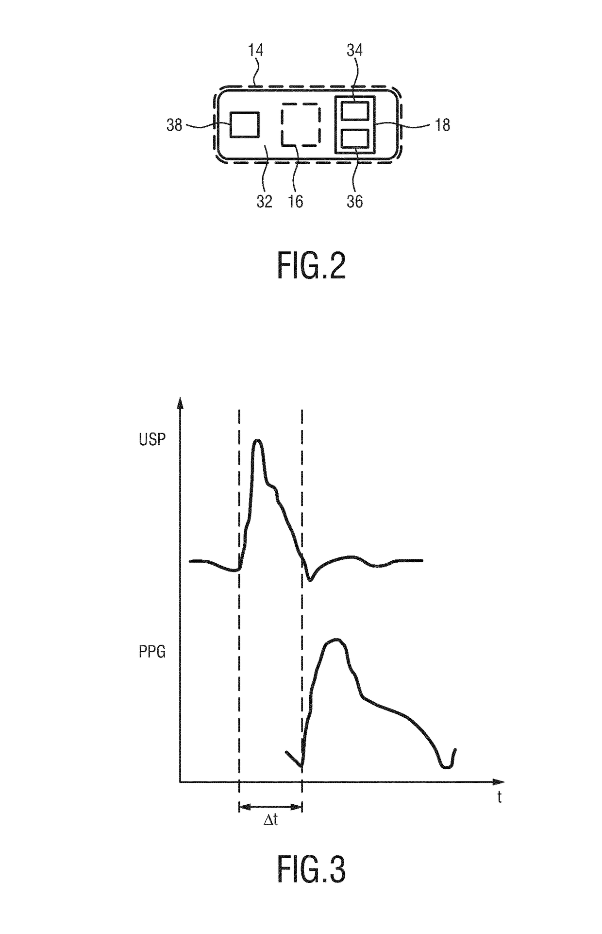
A monitoring apparatus for monitoring a blood pressure information of a subject is disclosed. The monitoring apparatus comprises an ultrasound transducer for emitting ultrasound waves to a volume of the subject that includes a blood vessel and for receiving ultrasound waves from said volume of the subject, and for providing a first signal on the basis of ultrasound waves received from the volume of the subject. A light source is included for emitting light to the subject and a light sensor is included for detecting light received from the subject and for providing a second signal on the basis of the light received from a skin of the subject. The monitoring apparatus comprises a processing unit for determining: i) a time of arrival of a cardiac pulse in the blood vessel based on the first signal, ii) a point in time when the cardiac pulse reaches the skin of the subject based on the second signal, iii) a pulse transit time between the time of arrival of the cardiac pulse PPG in the blood vessel and the point in time when the cardiac pulse reaches the skin of the subject; and iv) the blood pressure based on the pulse transit time.

Description

FIELD OF THE INVENTION[0001]The present invention relates to a monitoring apparatus for monitoring vital sign information of a subject.[0002]The present invention further relates to a monitoring method for monitoring vital sign information of a subject.[0003]The present invention in particular relates to the determination of a blood pressure as the vital sign information of the subject.BACKGROUND OF THE INVENTION[0004]Blood pressure is an important vital sign information to monitor diseases of a patient. Common measurement methods are performed either discontinuously by means of a cuff, which is cumbersome and uncomfortable for the user or continuously by means of an arterial line, which is invasive and increases the risk of an infection. An alternative method for measuring the blood pressure non-invasively and continuously is based on the measurement of a pulse wave velocity, wherein the velocity at which a heartbeat-induced pressure pulse travels through the vasculation is determi...

Claims


Application Information

Patent Timeline
IPC IPC(8): A61B8/04A61B5/021A61B5/02A61B5/00A61B8/06A61B8/08A61B8/00
CPCA61B8/04A61B5/02125A61B5/02007A61B5/6832A61B8/06A61B8/488A61B8/42A61B8/4416A61B8/5261A61B5/02416A61B2560/0223A61B5/0261
Inventor BEZEMER, RICKMATHEW, DENNYKROON, BART
Owner KONINKLJIJKE PHILIPS NV
Learn More