Device for visually indicating a blood pressure

a technology of visual indication and blood pressure, applied in the field of indicators, can solve the problems of not being usable for all, not being able to easily observe fluctuations, and soiling the environment around the patient to an undesirable extent, so as to achieve safe and correct deployment and less blood flow

Inactive Publication Date: 2010-02-02
ST JUDE MEDICAL COORDINATION CENT
View PDF22 Cites 30 Cited by
  • Summary
  • Abstract
  • Description
  • Claims
  • Application Information

AI Technical Summary

Benefits of technology

[0008]An object of the present invention is therefore to provide a means for visual Indication that an insertion tube for a wound closure has been correctly positioned inside a blood vessel (i.e., verification of correct position), such that the closure element can be deployed safely and correctly, and whereby less blood flows from the puncture wound than compared to prior art procedures.
[0009]The device is usable together with a system for deploying and attaching a wound closure member, said device being connectable to an insertion tube of such a system, such that blood from a blood vessel in which the insertion tube is inserted can flow into the display device, for visually displaying the pulsation of the blood flowing into the device, thereby providing the desired verification.

Problems solved by technology

This method, although being relatively efficient, entails spillage of blood, which is inconvenient and may soil the environment around the patient to an undesirable extent.
However, a disadvantage with this device is that it will not be usable for all possible pressures that may be encountered.
Namely, if blood enters the chamber the meniscus of blood will be located inside the chamber, and fluctuations may not readily be observed, either because the difference in levels between fluctuations is too small, or because the chamber simply cannot be observed.

Method used


Image

  • Device for visually indicating a blood pressure
  • Device for visually indicating a blood pressure
  • Device for visually indicating a blood pressure

Examples


Embodiment Construction

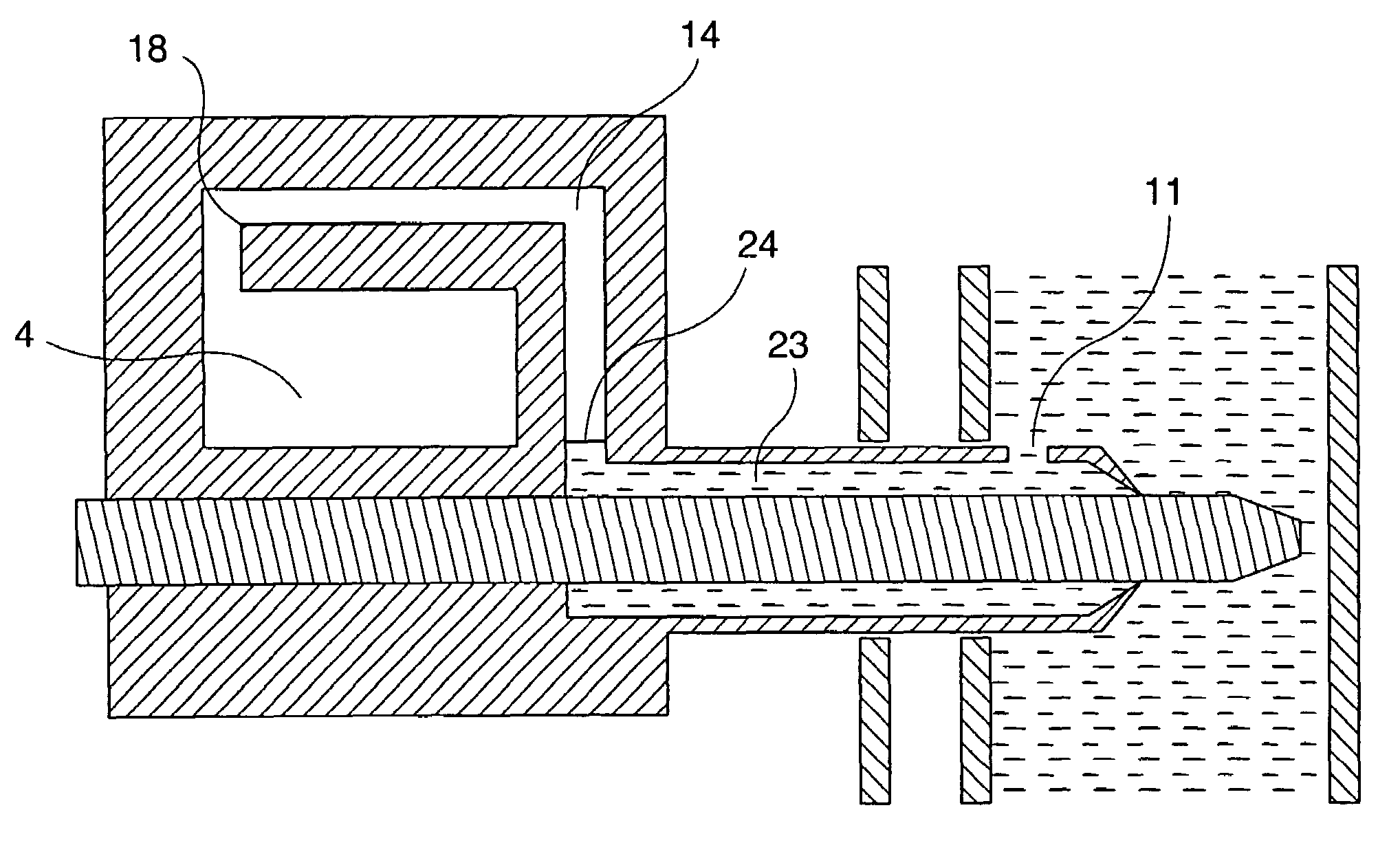
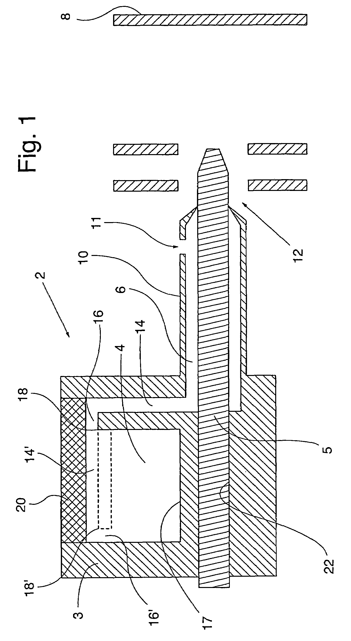
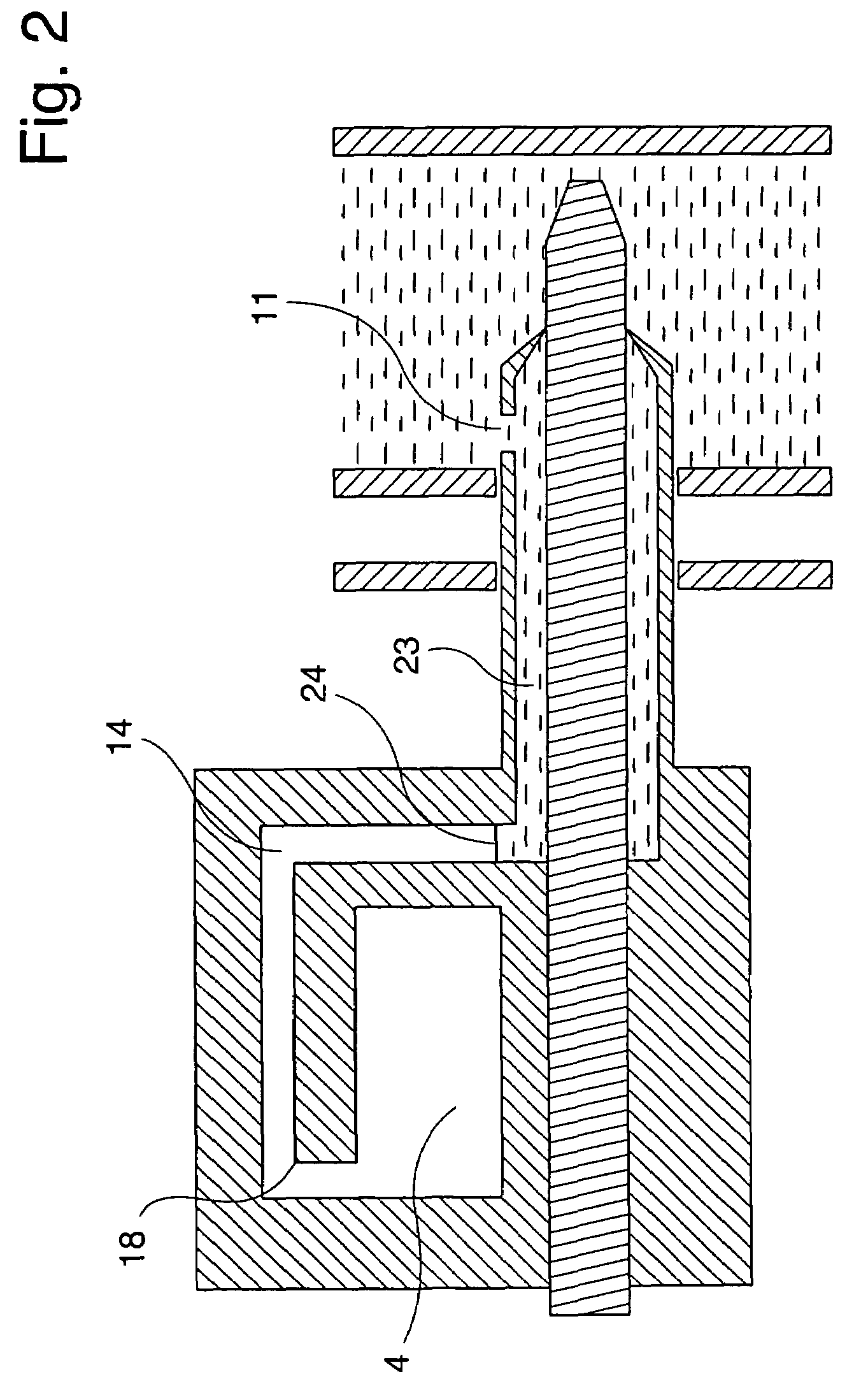
[0024]An indicator device for visually indicating a pressure of blood flowing inside a blood vessel according to the present invention, in its most general aspect, comprises a structure that, as an example, can be provided in the form of a body or handle to be gripped by a user of the device, inside which a duct extends. The duct has a distal end and a proximal end. A liquid inlet opening is provided at the distal end of the overall structure in fluid communication with the duct. The duct can extend all the way up to the distal end of the structure. The proximal end is sealed, such that no gas or liquid can escape from the duct at the proximal end. The distal end portion of the structure is adapted to be positioned inside the blood vessel. The inlet opening can be provided at the very distal tip of the distal end portion of the structure, or at a preferably known distance from the tip. The distal portion of the structure can be shaped as a tube which can have a suitable diameter for...


PUM


Abstract

An indicator device for visually indicating a pressure of blood inside a blood vessel includes: a body, the body comprising a duct extending in the body and having a sealed proximal end; a distal end portion adapted to be positioned inside the blood vessel and including a liquid inlet opening in fluid communication with the duct; and a window including an at least semi-transparent section configured to enable visual observation of blood entering into the duct via the inlet opening when the inlet opening is located inside the blood vessel.

Description

CROSS-REFERENCE TO RELATED PATENT APPLICATIONS[0001]The present application claims priority to U.S. Provisional Application No. 60 / 439,800, filed on Jan. 14, 2003, the contents of which are hereby incorporated by reference.FIELD OF THE INVENTION[0002]The present invention relates to an indicator device for visually indicating a pulsating pressure of blood flowing inside a blood vessel, and a method, the device and method being usable for verifying correct positioning of an insertion tube for a wound closure element and of the wound closure element itself inside the blood vessel, in the process of closing a puncture in the blood vessel.BACKGROUND OF THE INVENTION[0003]A system for sealing a percutaneous puncture in a vessel can comprise an inner seal, which is adapted to be positioned against an inner surface of the vessel wall, and a locking member, which is connected to the inner seal by, for example, a filament or a suture and which is adapted to be positioned against an outer sur...

Claims


Application Information

Patent Timeline
Patent Type & Authority Patents(United States)
IPC IPC(8): A61B5/02A61B5/00A61M5/178A61B17/12A61B5/0215A61B5/023A61B17/00A61B19/00A61M31/00
CPCA61B5/0215A61B17/0057A61B5/023A61B2017/00637A61B2017/00659A61B2017/00672A61B2019/464Y10S604/90A61B2090/064
Inventor EGNELOV, PERPREINITZ, FREDRIKFUCHS, JAMESANG.KERFELDT, DANTENERZ, LARS
Owner ST JUDE MEDICAL COORDINATION CENT
Why Eureka
Try Eureka