Method and casting/rolling system for casting and rolling a continuous strand material

A technology for rolling equipment and continuous casting billets, which is applied to driving devices for metal rolling mills, metal rolling, metal rolling, etc., and can solve the problems of not proposing detailed implementation plans for technical teaching, disadvantages, etc.

Active Publication Date: 2017-08-18
SMS GRP GMBH
View PDF12 Cites 2 Cited by
  • Summary
  • Abstract
  • Description
  • Claims
  • Application Information

AI Technical Summary

Problems solved by technology

However, said patent document does not propose an exhaustive implementation of this technical teaching
However, a more detailed consideration of this solution reveals the disadvantage that the main drive with a powerful rolling train of several megawatts must follow the implementation of a continuous casting machine with a drive of only a few kilowatts, which predetermines The exit speed of continuously cast billets from the continuous casting machine
This is disadvantageous in terms of control technology, since the performance in terms of control technology, ie the dynamics of the drive, decreases with the size of the motor

Method used


Image

  • Method and casting/rolling system for casting and rolling a continuous strand material
  • Method and casting/rolling system for casting and rolling a continuous strand material
  • Method and casting/rolling system for casting and rolling a continuous strand material

Examples


Embodiment Construction

[0040] Refer to the following in the form of an embodiment Figures 3 to 6 The present invention is described in detail.

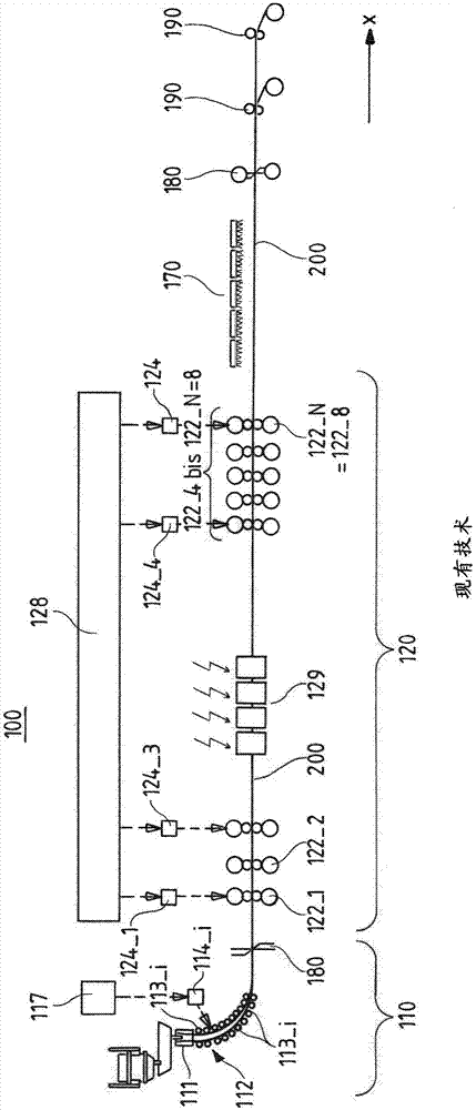
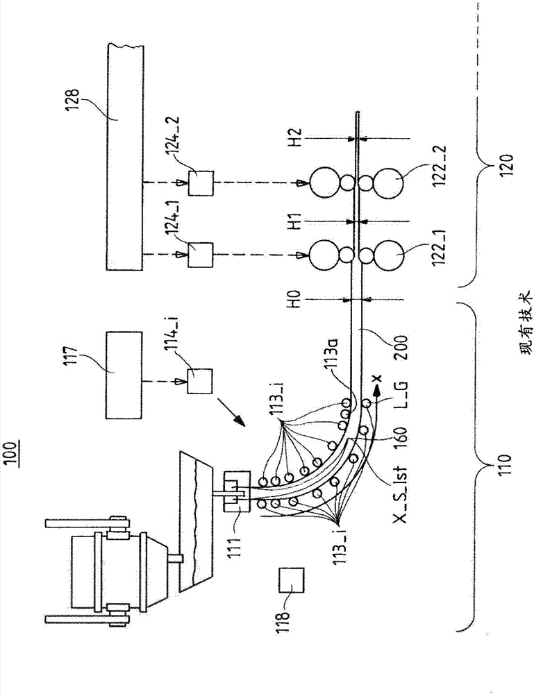
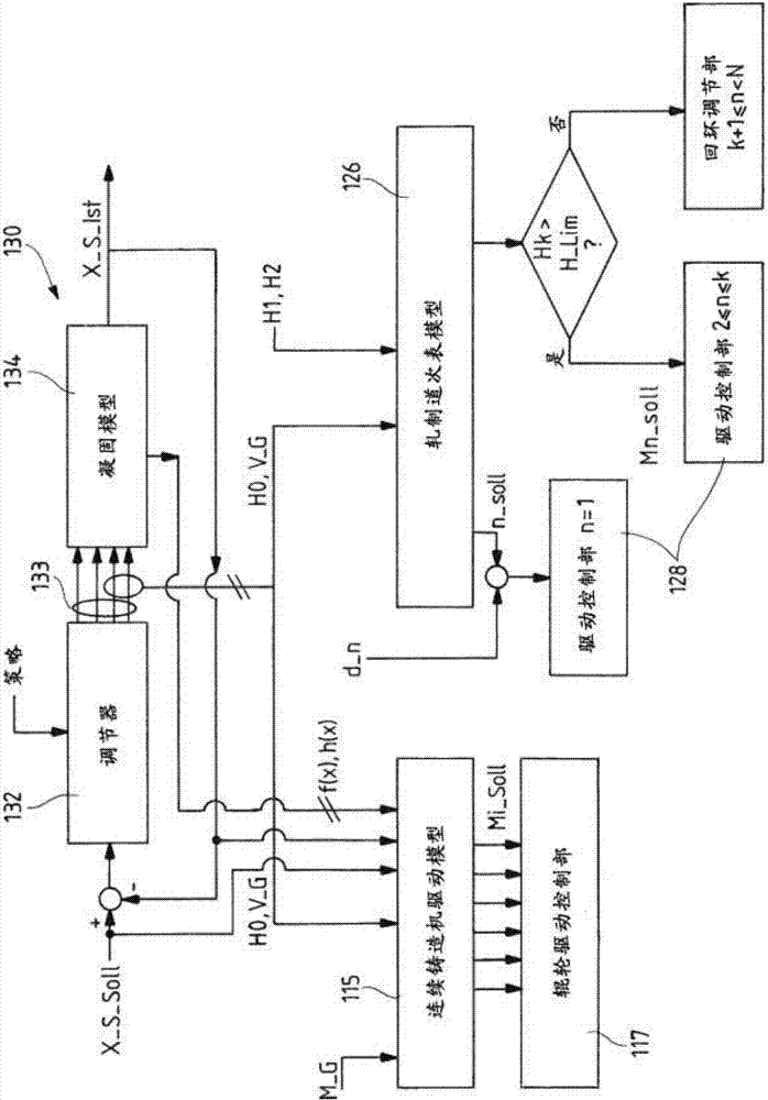
[0041] image 3 A diagram according to the invention for actuating drives in a continuous casting machine 110 and in a rolling train 120 is shown. The starting point of the solution according to the invention is the control circuit 130 for setting the position of the wick tip to a predetermined setpoint position X_S_Soll within the slab guide 112 . The target position X_S_Soll corresponds to the predetermined position of the path component x. The wick tip control circuit 130 is designed to simulate or theoretically calculate the respective current actual position of the wick tip 130 with the aid of a solidification model 134 , which forms a control section of the wick tip control circuit 130 . The thus determined actual position X_S_Ist is compared with a predetermined target position X_S_Soll and a deviation which may be determined during the compariso...


PUM


Abstract

The invention relates to a method for operating a casting / rolling system 100 and to a corresponding system for casting and rolling an endless strand material 200. The casting / rolling system comprises a strand casting machine 110 and a rolling train arranged downstream of the strand casting machine. The method has the following step: controlling the drive 124 for the rollers of the first roller frame 122_1 of the rolling train by means of a drive control 124 in response to a target value specification of the pass sequence model 126. Furthermore, the drive 114 of the at least one strand guiding roller 113 is controlled by a strand guiding roller drive control 117 in response to a target value specification of the strand casting machine drive model 115. The aim of the invention is to synchronize the drives of both the strand casting machine and of the rolling train in a superordinated manner with respect to a mass flow with an equal and constant value in the two aforementioned system parts. This is achieved in that the pass sequence model 126 specifies a target rotational value for the drive 124_1 of the first roller frame 122_1 as a target value specification, and the strand casting machine drive model 115 specifies a target torque for the drive 114_i of the at least one driven strand guiding roller 113_i as a target value specification.

Description

technical field [0001] The invention relates to a method and a casting and rolling plant for the casting and rolling of endless cast strands from metal, in particular steel. Background technique [0002] For example, in figure 1 A known casting and rolling plant for casting and rolling endless cast slabs is shown in . The casting and rolling equipment 100 shown here comprises a continuous casting machine 110, a rolling train 120 connected after the continuous casting machine, a cooling section 170 connected after the rolling train, a dividing device 180 connected after the cooling section, and a Coiler 190 for rolling up continuous casting billet 200 . Specifically, the continuous casting machine 110 includes a mold 111 , a slab guide 112 arranged after the mold 111 , and typically a dividing device 180 . The splitting device 180 is used for splitting the so-called cooling cast slab. At the initially cooled walls of the mold 111 , the melt solidifies in the mold and in t...

Claims


Application Information

Patent Timeline
Patent Type & Authority Applications(China)
IPC IPC(8): B21B1/46B21B38/00B21B37/00B22D11/14B22D11/16
CPCB21B1/463B21B37/00B21B38/00B22D11/142B22D11/16B21B37/46B21B2037/002B22D11/1206B22D11/124B22D11/1282B22D11/20B21B11/00B21B37/26B21B2275/12B22D11/0622B22D11/1226B22D11/128B22D11/143
Inventor M·布罗伊尔A·魏尔
Owner SMS GRP GMBH
Why Eureka
Try Eureka