
Handling device with suction cup for foodstuff

A technology for operating devices and food, applied in the direction of transportation and packaging, conveyor objects, load hanging elements, etc., which can solve the problems of time-consuming and expensive

Active Publication Date: 2017-08-18
PAIBO CO LTD
View PDF8 Cites 3 Cited by
  • Summary
  • Abstract
  • Description
  • Claims
  • Application Information

AI Technical Summary

Problems solved by technology

This repair procedure is time consuming and expensive, depending on the number and complexity of the parts being replaced

Method used


Image

  • Handling device with suction cup for foodstuff
  • Handling device with suction cup for foodstuff
  • Handling device with suction cup for foodstuff

Examples


Embodiment Construction

[0049] Hereinafter, the same elements are denoted by the same numerals and reference numerals and elements shown in more than one drawing will not be described repeatedly.

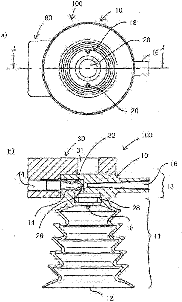
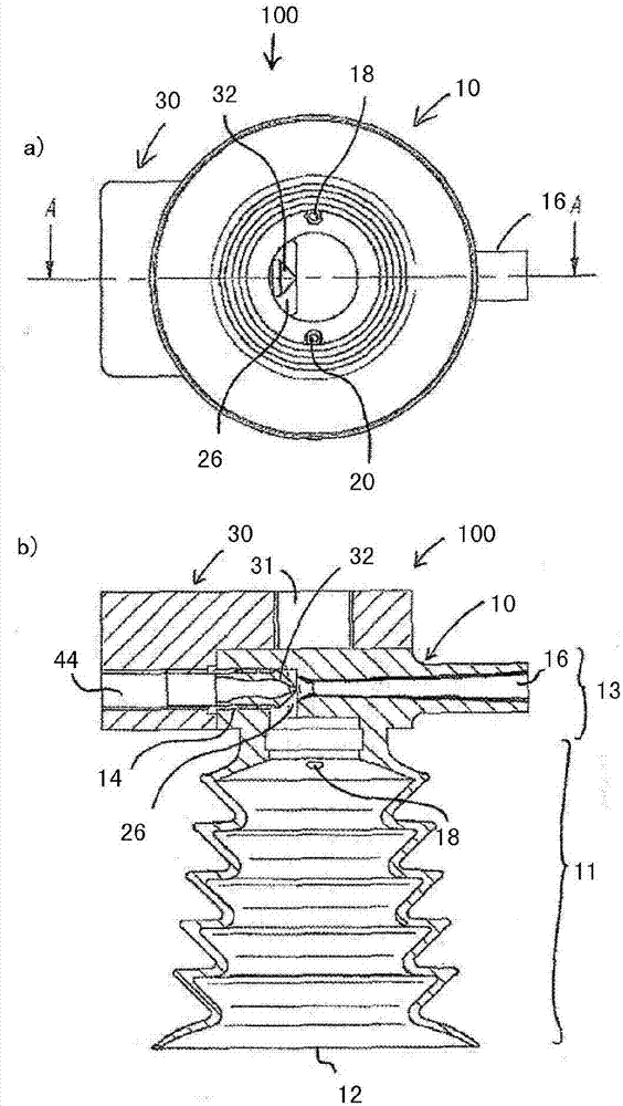
[0050] figure 1 a shows a bottom view of a first embodiment of an operating device 100 comprising a suction cup 10 and a plug connector 30 . The details of the suction cup 10 and the plug connector 30 will become clearer with reference to the following figures and descriptions.

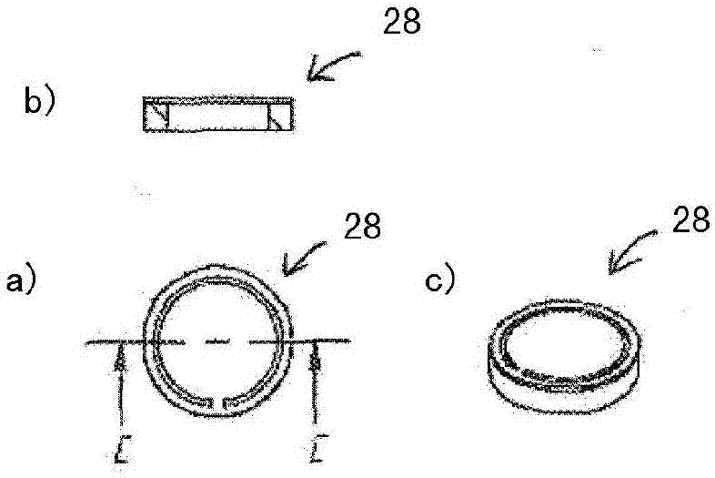
[0051] figure 1 The schematic diagram of the handling device 100 at a shows the interior of the suction cup 10 seen from below, ie its open end configured to contact the food product to be handled. In addition to the walls constituting the actual suction cup, the suction cup 10 comprises an outlet nozzle 16 located in the upper region of the suction cup 10 on the opposite side of the plug 30 attached to the suction cup 10 . exist figure 1 The check valve 28 is seen in a, which is located at the top of the actual suction cup an...


PUM


Abstract

The present invention relates to a handling device (100) for handling foodstuff, comprising a suction cup (10) and a docking piece (30) supporting the suction cup, wherein the suction cup (10) is removably attached to the docking piece (30), wherein the docking piece (30) comprises a drive nozzle (32) inserted into the suction cup (10) attached to the docking piece (30) for ejecting a fluid from the drive nozzle (32) inside of the suction cup (10), and wherein the suction cup (10) comprises a drive opening (14) for receiving the drive nozzle (32) of the docking piece (30), an outlet nozzle (16) having at least one constriction which outlet nozzle (16) is aligned with the drive nozzle (32), so that the drive nozzle (32) and the outlet nozzle (16) cooperate to form an ejector, and a suction opening (12) for applying a suction force provided by the ejector to a surface of the foodstuff to be handled.

Description

technical field [0001] The invention relates to a suction cup for handling food, a plug configured to support the suction cup, and an handling device configured for attachment to a handling device for handling food. Background technique [0002] Known vacuum pumps use compressed air sources or other high-pressure fluid sources to generate negative pressure or vacuum in the surrounding space. The surrounding space can be set as the inlet part of the pump to communicate with other parts or interfaces of the pump (such as suction cups) to apply vacuum to it. objects. Compressed air driven injectors operate by accelerating high pressure air through the driven nozzle and ejecting it as an air jet at high velocity across the gap between the driven nozzle and the outlet runner or nozzle. Fluid medium in the surrounding space (eg inlet section) between the drive nozzle and the outlet nozzle is conveyed into the high velocity stream of compressed air, and the conveying medium and th...

Claims


Application Information

Patent Timeline
Patent Type & Authority Applications(China)
IPC IPC(8): B65G47/91
CPCB65G47/91B66C1/02
Inventor P·特尔
Owner PAIBO CO LTD
Learn More