Stop damper

A technology for shock absorbers and stoppers, applied in the direction of shock absorbers, springs/shock absorbers, shock absorbers, etc., can solve problems such as limitations of shock absorption characteristics, achieve low structural cost, and be conducive to economical production.

Active Publication Date: 2017-08-18
THYSSENKRUPP PRESTA AG
View PDF6 Cites 1 Cited by
  • Summary
  • Abstract
  • Description
  • Claims
  • Application Information

AI Technical Summary

Problems solved by technology

[0006] A disadvantage of the stop dampers known from the prior art is that, for specific material properties, such as elasticity, hardness, retu

Method used


Image

  • Stop damper
  • Stop damper
  • Stop damper

Examples


Embodiment Construction

[0027] Identical components in different figures are always marked with the same reference numerals and are therefore generally only indicated or mentioned once.

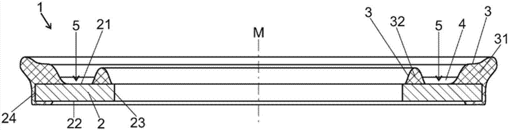
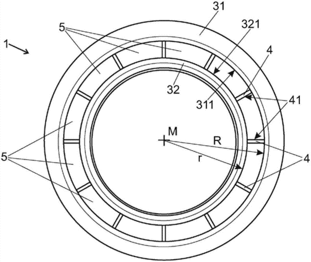
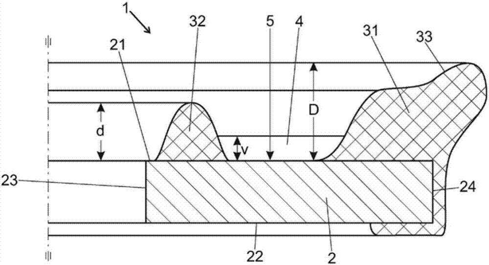
[0028] The stop damper 1 according to the invention is designed in the form of a ring or disk with a central axis M. The stop damper 1 comprises a carrier 2 which is formed in the form of an annular disk with a first front side 21 and a second, opposite front side 22 and inner and outer side surfaces 23 and 24 extending therebetween. The bracket 2 is preferably made of a bend-resistant, durable metal or plastic material.

[0029] On the first front side of the support 2 is mounted a shock absorbing element 3, preferably made of an elastomeric material, such as synthetic rubber and nitrile-butadiene rubber, which is softer than the material of the support 2 . The damping element 3 is bonded to the support 2 on the contact surface of the damping element, for example glued or sintered.

[0030] The damping element 3...


PUM


Abstract

The present invention relates to a stop damper comprising an annular support element (2) which has a first and a second axial end face (21 and 22) and lateral faces (23, 24) extending therebetween. At least one damping element (3) consisting of an elastic material is attached to at least the first end face (21), said element projecting in the axial direction from the end face (21). In order to provide a stop damper with improved options for the design of the damping characteristics, according to the invention the damping element (3) has at least one axially continuous opening (5) in the annular surface region of the support element (2).

Description

technical field [0001] The invention relates to a stop damper comprising an annular support element having first and second axial front faces and side faces extending therebetween, wherein at least one spring made of elastic material is mounted on at least the first front face. A shock absorbing element is formed, and the shock absorbing element protrudes from the front in the axial direction. [0002] Stop dampers of the above-mentioned type are used in vehicle steering in which an axially movable element in the steering gear, usually a toothed rack, is connected on both sides to the tie rod via an axial ball joint . The maximum possible steering movement of the steering gear is defined in such a way that when the rack is maximally moved axially relative to the steering gear, said axial ball joints are aligned axially with the corresponding shaft of the steering housing. Collide with the corresponding contact surface. Background technique [0003] In order to avoid undes...

Claims


Application Information

Patent Timeline
IPC IPC(8): F16F7/00F16F1/377F16C11/06B62D3/12
CPCB62D3/12F16C11/0652F16F1/377F16F7/00F16F1/3732
Inventor 赫尔穆特·莫尔纳
Owner THYSSENKRUPP PRESTA AG
Why Eureka
Try Eureka