Engine control valve in a motor vehicle
A technology for motor vehicles and engines, which is applied in the direction of machines/engines, engine components, lift valves, etc., and can solve problems such as increasing manufacturing costs
- Summary
- Abstract
- Description
- Claims
- Application Information
AI Technical Summary
Problems solved by technology
Method used
Image
Examples
Embodiment Construction
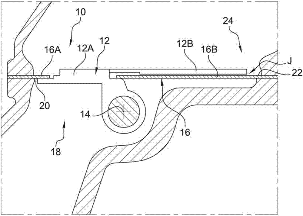
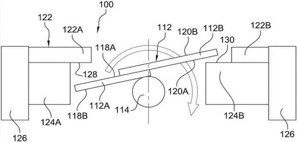
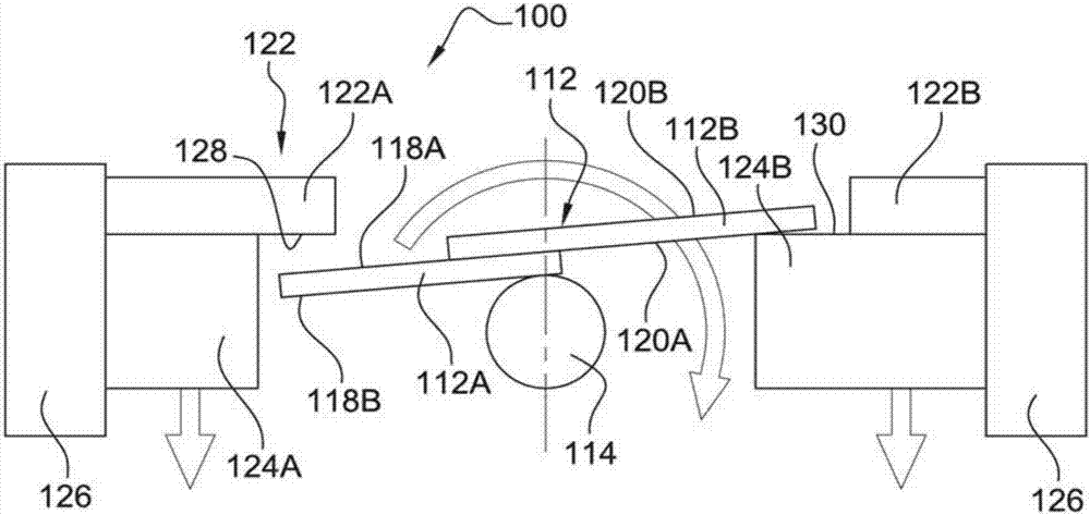
[0022] now refer to figure 2 , which shows an engine control valve 100 according to the invention comprising a valve flap 112 mounted in a pivotal manner about an axis of rotation 114 . The valve flap 112 includes a first portion 112A and a second portion 112B interconnected at an axis of rotation 114 . The first portion 112A and the second portion 112B of the valve flap 112 are parallelepiped-shaped in cross-section. The first portion of the valve flap 112 includes opposed first and second planar surfaces 118A, 118B. Similarly, the second portion 112B of the valve flap 112 includes opposed first and second planar surfaces 120A, 120B. One end of the first portion 112A of the valve flap 112 is arranged on the shaft 114 such that its first surface 118A is located opposite the shaft 114 with respect to its second surface 118B. The second portion 112B of the valve flap 112 bears at one end by its first planar surface 120A against the first planar surface 118A of the first port...
PUM
 Abstract
Description
Claims
Application Information
 - R&D
- Intellectual Property
- Life Sciences
- Materials
- Tech Scout
- Unparalleled Data Quality
- Higher Quality Content
- 60% Fewer Hallucinations
Browse by: Latest US Patents, China's latest patents, Technical Efficacy Thesaurus, Application Domain, Technology Topic, Popular Technical Reports.
© 2025 PatSnap. All rights reserved.Legal|Privacy policy|Modern Slavery Act Transparency Statement|Sitemap|About US| Contact US: help@patsnap.com


