
Device for cooling a shaft furnace distribution chute support journals

A trunnion and chute technology, which is used in the field of equipment for cooling shaft furnace distribution chute support trunnions

Active Publication Date: 2017-08-18
PAUL WURTH SA
View PDF5 Cites 0 Cited by
  • Summary
  • Abstract
  • Description
  • Claims
  • Application Information

AI Technical Summary

Problems solved by technology

Consequently, access to the front end face of the trunnion is no longer possible, so the cooling circuit is no longer connected to the trunnion cooling channel via a swivel joint fixed to said outer front end, as in the prior art

Method used


Image

  • Device for cooling a shaft furnace distribution chute support journals
  • Device for cooling a shaft furnace distribution chute support journals

Examples


Embodiment Construction

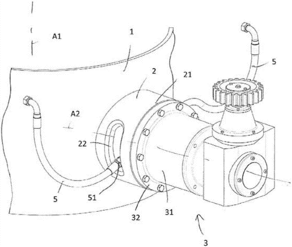
[0020] figure 1 The drawing of the figure shows the shell 1 of the blast furnace charging device, which can be rotated about the vertical axis A1 of the blast furnace, and the bearing 2 is attached to the shell, and the end of the bearing has a drive for pivoting about the horizontal axis A2 The reduction gear unit 3 of the chute (not shown). The reduction gear unit 3 includes a crankcase 31 fixed to the outer end 21 of the bearing 2 by a flange (flange) 32 .

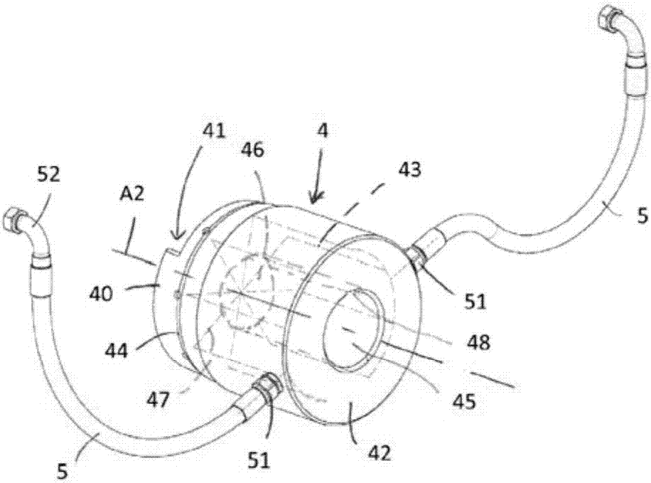
[0021] figure 2 The trunnion 4 for supporting the chute shown in includes a housing 41 oriented towards the inner end 40 of the trunnion, towards the axis A1, the housing being arranged to accommodate the support lugs of the chute, the chute's The support lug is held rigidly in the receptacle in a manner known per se. The other end of the trunnion 42 is rigidly connected to the output shaft of the reduction gear unit 3 , which is rotatably supported and guided in the crankcase 31 . For this purpose, the trunnion co...


PUM


Abstract

Device for cooling the support journals (4) of a distribution chute of an installation for charging a shaft furnace, such as a blast furnace, the chute being mounted with the ability to pivot about a horizontal axis (A2) on a ring (1) coaxial with the furnace, the chute being connected in rotation to the journals which are rotated by drive means, being for example connected directly in terms of rotation via their ends (42) to output shafts of reduction gear (3) and comprising internal cooling ducts (43). The cooling device comprises feed and return pipes (5) for the cooling water circulating through the internal ducts, the feed and return pipes (5) being connected to the journals (4) by couplings (51) fixed to the cylindrical surface of the journals, and the feed and return pipes (5) are designed to allow the rotary movement of the couplings (51) about the axis of pivoting of the chute when the chute pivots, notably by passing through oblong slots (22) extending circumferentially in the wall of bearings (2) supporting the driving reduction gear.

Description

technical field [0001] The invention relates to a device for cooling a support trunnion of a distribution chute for a charging device of a shaft furnace, such as a blast furnace. Background technique [0002] Such equipment usually comprises a fixed feed channel arranged vertically in the center of the furnace throat centered on the vertical axis of the furnace, and a distribution chute for distributing the The filling material arriving at the channel mentioned above. In order to be able to distribute the filling material rationally, the distribution chute can be rotated about said vertical axis and pivoted about a horizontal axis. To this end, the chute is typically mounted pivotably about said horizontal axis in a housing coaxially mounted about said feed channel and rotatable about a vertical axis. The chute is pivotally mounted in the housing by means of a generally cylindrically shaped trunnion having a horizontal axis, to which the chute is fixed, and which is rotata...

Claims


Application Information

Patent Timeline
Patent Type & Authority Applications(China)
IPC IPC(8): F27B1/20F27B1/24
CPCF27B1/20F27B1/24C21B7/20C21B7/10
Inventor 保罗·托科尔特哈拉尔德·朗
Owner PAUL WURTH SA
Learn More