Pressure change measurement device, altitude measurement device, and pressure change measurement method
A technique for measuring device, pressure, applied in the direction of measuring device, height/level measurement, pressure difference measurement between multiple valves, etc.
- Summary
- Abstract
- Description
- Claims
- Application Information
AI Technical Summary
Problems solved by technology
Method used
Image
Examples
no. 1 approach
[0056] (1-1: overall structure)
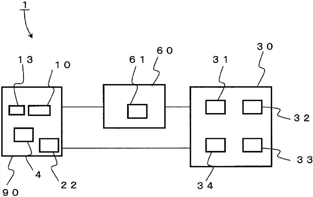
[0057] figure 1 The structure of the pressure change measurement device 1 according to the first embodiment of the present invention is shown.
[0058] The pressure change measuring device 1 of the first embodiment has: a differential pressure sensor 90; a signal generation reference value signal; and an arithmetic processing unit 30 that calculates a change in the measurement target pressure based on the output signal of the differential pressure sensor 90 and the reference value signal set by the reference value setting unit 60 .
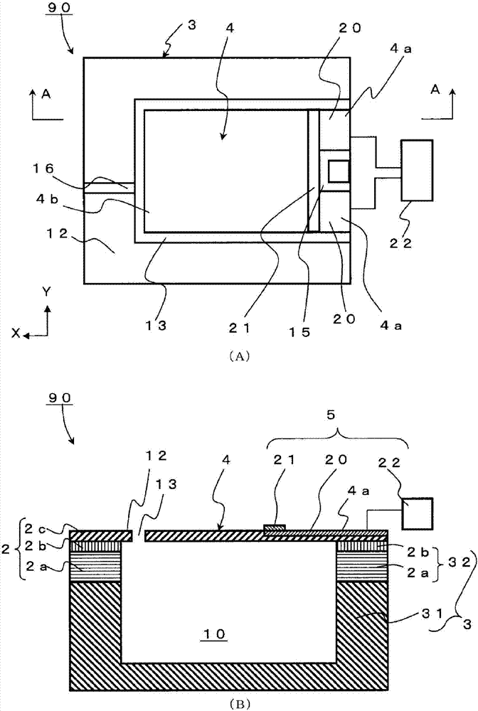
[0059] The detailed structure of the differential pressure sensor 90 will be described later, and it has a chamber 10, a gap 13 that is a communication hole through which the pressure transmission medium that transmits the pressure of the measurement object flows inside and outside the chamber 10, and the internal pressure of the measurement chamber 10 and the pressure of the measurement object. The cantilever 4...
no. 2 approach
[0145] use Figure 11 The pressure change measuring device 1 of the second embodiment will be described. In addition, for the same structures as those of the pressure change measuring device of the first embodiment, the same names and symbols are used, and descriptions thereof are omitted.
[0146] (2-1: Overall structure)
[0147] Here, in the pressure change measurement device 1 of the second embodiment, the difference from the pressure change measurement device 1 of the first embodiment is that the reference value setting unit 60 constituting the pressure change measurement device 1 is composed of a determination unit 61, The detection unit 62 and a storage device (not shown) are configured.
[0148] The detection unit 62 is composed of a sensor and a detector that detect whether or not there is a change in the external pressure Pout. Furthermore, like the first embodiment, the determination unit 61 has a function of calculating and updating a reference value based on th...
no. 3 approach
[0169] use Figure 14 The pressure change measuring device 1 of the third embodiment will be described. In addition, for the same structure as the pressure change measurement device of the said 1st and 2nd embodiment, the same name and code|symbol are used, and the description is abbreviate|omitted.
[0170] (3-1: Overall structure)
[0171] Here, in the pressure change measurement device 1 of the third embodiment, the difference from the pressure change measurement devices 1 of the first and second embodiments is that the reference value setting unit 60 is composed of a determination unit 61 , a pressure adjustment unit 63 , Storage device (illustration omitted). Furthermore, a user interface (not shown) for receiving a reference value setting instruction from a user is connected to the determination unit 61 . and then, Figure 14 The shown pressure regulator 63 is a valve capable of opening and closing a vent hole provided between the chamber 10 and the outside in the di...
PUM
 Abstract
Description
Claims
Application Information
 - R&D
- Intellectual Property
- Life Sciences
- Materials
- Tech Scout
- Unparalleled Data Quality
- Higher Quality Content
- 60% Fewer Hallucinations
Browse by: Latest US Patents, China's latest patents, Technical Efficacy Thesaurus, Application Domain, Technology Topic, Popular Technical Reports.
© 2025 PatSnap. All rights reserved.Legal|Privacy policy|Modern Slavery Act Transparency Statement|Sitemap|About US| Contact US: help@patsnap.com


