
Welding and positioning device for special-shaped parts in straight cylinder

A technology for welding positioning and special-shaped parts, which is used in welding equipment, auxiliary devices, auxiliary welding equipment, etc., can solve the problems of inaccurate welding positioning, unable to meet production needs, affecting assembly quality, etc., to achieve short positioning time and reduce assembly. Cost, simple structure effect

Active Publication Date: 2019-11-12
CHANGZHI QINGHUA MACHINERY FACTORY +1
View PDF8 Cites 0 Cited by
  • Summary
  • Abstract
  • Description
  • Claims
  • Application Information

AI Technical Summary

Problems solved by technology

At present, the welding positioning of the parts in the cylinder is generally carried out by hoisting the parts assembled with the installation block into the cylinder through the crane, after adjusting the position of the assembly parts, marking the assembly position of the parts in the cylinder, and completing the welding of the parts in the cylinder Positioning, this welding positioning method takes a long time, cannot accurately position the welding, and needs to repeatedly use the crane to transfer the parts, the labor intensity is high, and after the parts in the cylinder are welded, there are welding deformations and positioning defects, which affect the assembly quality , cannot meet the current production needs of the enterprise

Method used


Image

  • Welding and positioning device for special-shaped parts in straight cylinder
  • Welding and positioning device for special-shaped parts in straight cylinder
  • Welding and positioning device for special-shaped parts in straight cylinder

Examples


Embodiment Construction

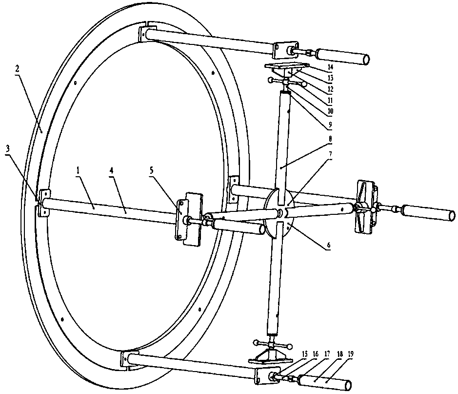
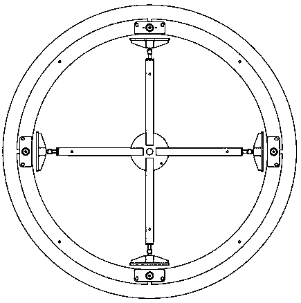
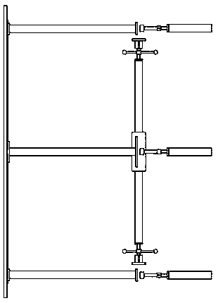
[0021] Such as Figure 1-Figure 3 As shown, the welding and positioning device for special-shaped parts in a straight cylinder of the present invention includes a flange 2, four positioning rod combinations 1, four support rod combinations 6 and four ejector rod combinations 19;

[0022] Four key grooves are evenly distributed along the circumferential direction on the annular surface of the flange 2;

[0023] The positioning rod combination 1 includes a positioning plate 3, a positioning rod 4 and a support plate 5, the positioning rod 4 is horizontally arranged, one end is connected with the positioning plate 3, and the other end is connected with the support plate 5;

[0024] Described strut assembly 6 comprises support rod 8, adjustment screw rod 10, adjustment handle 11, briquetting block 12 and pressing plate 14, and one end of support rod 8 is fixed with the first plug 9 with threaded hole, and one end of adjustment screw rod 10 is threaded Connected with the first plu...


PUM


Abstract

The invention discloses a welding locating device for special-shaped parts in a straight barrel and belongs to the technical field of welding locating equipment. The welding locating device for the special-shaped parts in the barrel aims at achieving the technical effects that locating is conducted precisely, assembling quality is high, and labor intensity is low. According to the technical scheme, the welding locating device comprises a flange, four locating rod assemblies, four supporting rod assemblies and four jacking rod assemblies; four key grooves are uniformly formed in the circular face of the flange in the circumferential direction; locating plates in the four locating rod assemblies are provided with keys, the keys are connected with the four key grooves in the flange correspondingly, jacking rods in the four jacking rod assemblies are arranged to be coaxial with locating rods in the four locating rod assemblies correspondingly, and supporting plates in the locating rod assemblies are arranged to be opposite to jacking blocks in the jacking rod assemblies; and the four supporting rod assemblies and a connection supporting plate are located among the four locating rod assemblies, and pressing plates in the four supporting rod assemblies face the supporting plates in the four locating rod assemblies and the jacking blocks in the four jacking rod assemblies correspondingly. The welding locating device is used for conducting welding locating on the parts in the barrel.

Description

technical field [0001] A welding positioning device for special-shaped parts inside a straight cylinder belongs to the technical field of welding positioning equipment, in particular to a welding positioning device for special-shaped parts. Background technique [0002] At present, in large-scale equipment manufacturing enterprises, the welding positioning requirements of the parts in the cylinder are relatively high, and the structure of the parts in the cylinder is complex. The welding positioning accuracy of the parts directly affects the welding quality of the parts and the accuracy of the parts in the subsequent process. assembly. At present, the welding positioning of the parts in the cylinder is generally carried out by hoisting the parts assembled with the installation block into the cylinder through the crane, after adjusting the position of the assembly parts, marking the assembly position of the parts in the cylinder, and completing the welding of the parts in the...

Claims


Application Information

Patent Timeline
Patent Type & Authority Patents(China)
IPC IPC(8): B23K37/04
CPCB23K37/04B23K37/0443
Inventor 陈霞常军李金荣和哲范伟利王江勇郑娜娜
Owner CHANGZHI QINGHUA MACHINERY FACTORY
Learn More