Device and method for machine control

a machine control and device technology, applied in the direction of mechanical measuring arrangements, instruments, manufacturing tools, etc., can solve the problem of extremely time-consuming and labor-intensive data base search process, and achieve the effect of convenient compression

Active Publication Date: 2008-01-15
WALTER MASCHINENBAU GMBH
View PDF21 Cites 6 Cited by
  • Summary
  • Abstract
  • Description
  • Claims
  • Application Information

AI Technical Summary

Benefits of technology

[0008]The machine control device according to the invention assists the programmer in the input or determination of travel paths requiring a short positioning time. Said machine control device can also be equipped to determine such travel paths automatically. The characteristic of the machine control device and the associated control method is based on the fact that a pre-computed data base is provided, which applies to the separated working area and which contains a collision parameter for each tool and each tool position as well as for each workpiece and each workpiece position as well as for each separation element of the working area. For example, this parameter is “zero” when there is no collision and “one” when the respective workpiece position and the tool position collide (whereby said tool position is determined by a location in the area of the machine coordinates), which means an overlapping path of tool and workpiece. If a special path of the workpiece is provided through the working area and / or of the tool through the working area, then there can be determined through a simple search of the data base whether the proposed path includes collisions or not. This can be achieved in the way of checking predetermined paths and it can also be a supporting measure during the determination of travel paths.
[0010]Determination of the collision parameters in the above-mentioned manner occurs preferably now for each separated type of tool in combination with each separated type of workpiece whereby preferably the geometric shape of the unfinished pieces are selected as workpieces. All these constellations are then entered into the data base. It has been shown that the computation of such a data base can take more than a day even on highly efficient computers. The data base forms then a lookup table through which a proposed path of a grinding tool and / or a workpiece can be checked for freedom from collision within a few seconds or even faster at a corresponding arrangement of data. The inventive method and the machine control device achieve thereby an individual basis to be able to check for freedom from collision during programming of travel paths or during the automatic creation of said travel paths. In particular, time-efficient travel paths can be determined very rapidly through repeat return to the data base.
[0014]The data base consists of an indexed listing, which means a chain of zeros appear in the rule. Said data base can thereby easily compressed from the start. Data compression can be performed and respectively limited to the pairing of tool types and workpiece types so that only a partial data base has to be decompressed (unpacked) to check freedom from collision of paths of a specific workpiece and of a specific tool.

Problems solved by technology

The search of the data base is an extremely time-intensive process, but it has to be performed only one time.

Method used


Image

  • Device and method for machine control
  • Device and method for machine control
  • Device and method for machine control

Examples


Embodiment Construction

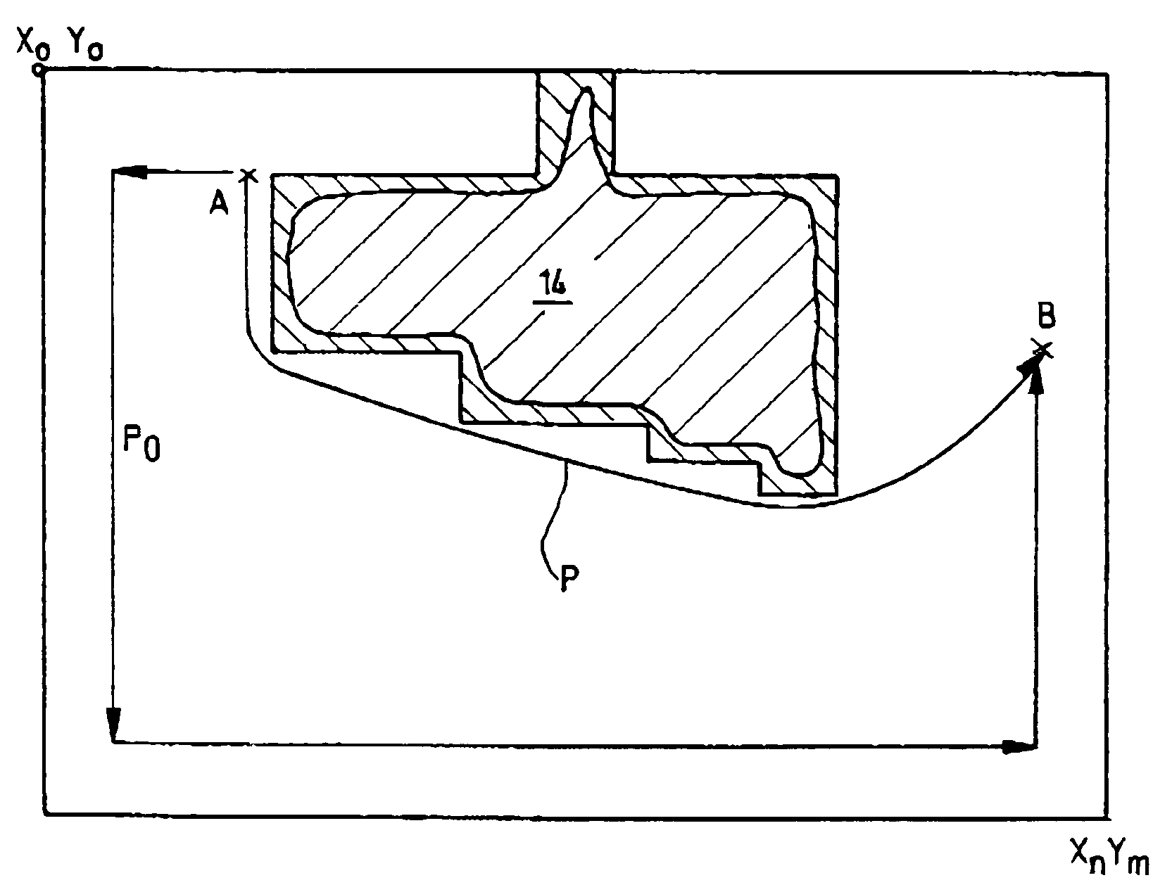
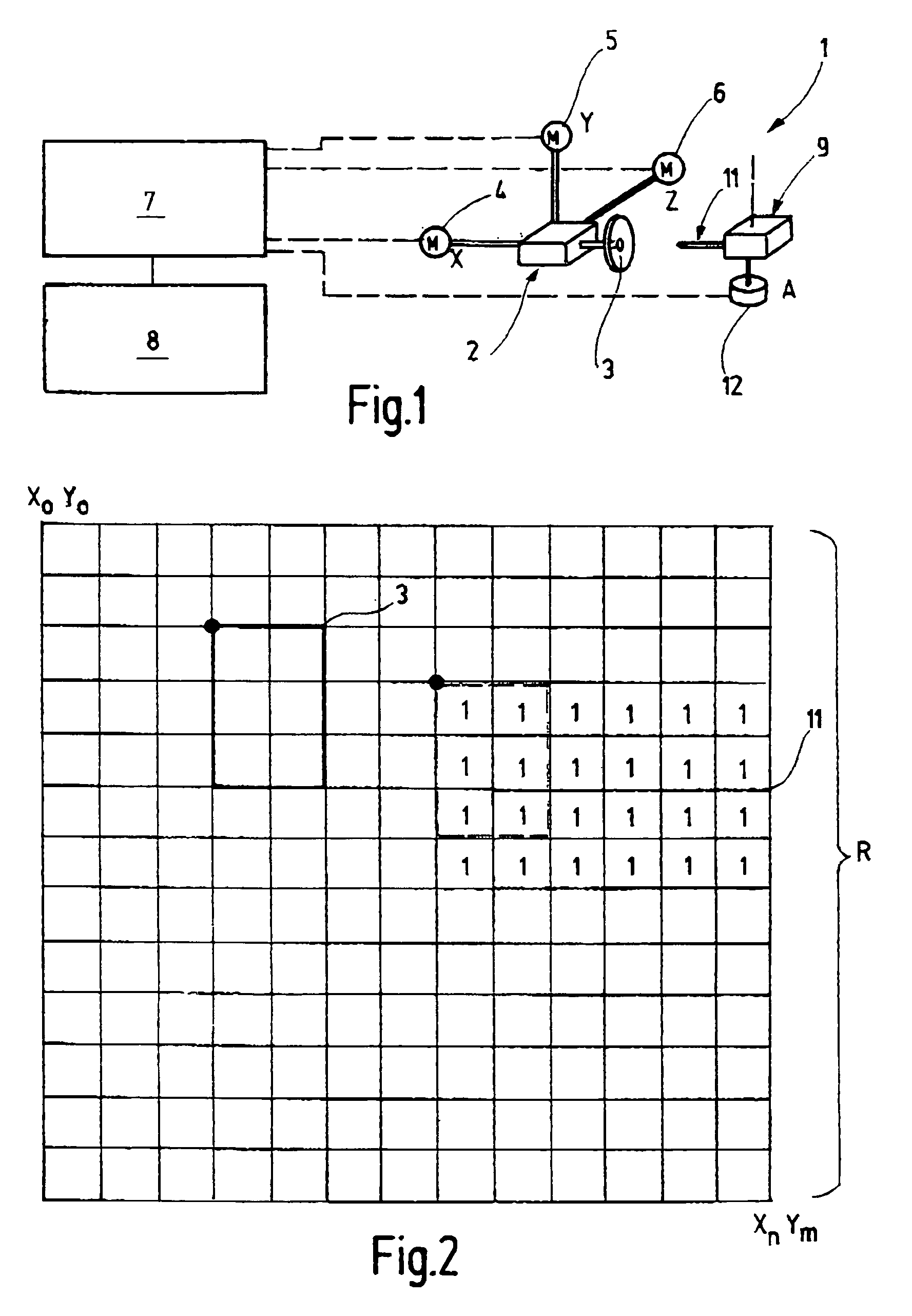
[0023]A grinding machine 1 is shown in FIG. 1 in a highly schematic illustration. Said grinding machine1 comprises a grinding spindle carrier 2 with a grinding tool 3, i.e. a grinding wheel. The grinding spindle carrier 2 can be adjusted linearly in several directions—for instance in three directions X, Y, Z. Corresponding drives 4, 5, 6 serve for adjustment whereby said drives are connected to a control device 7 via control lines. Said control device is a machine control computer, for example, which is connected to a memory unit 8. The grinding machine 1 comprises additionally a workpiece carrier 9 into which a rod-shaped unfinished piece 11 is mounted in FIG. 1 as an example. For example, the workpiece carrier 9 can be mounted rotatably about axis A. A corresponding drive 12 is connected to the control unit 7. If the grinding spindle carrier 2 is movable only in the Y and Z direction, then the workpiece carrier 9 may additionally be movable in X direction. The drive 4 is then conn...


PUM


Abstract

A data set (D) is provided for machine control of a grinding machine to determine time-efficient, collision-free travel paths. The data set has a collision parameter of “0” or “1” in each separate coordination point (X, Y, Z, A) as well as for each combination of the separated tool types (WZI) and workpiece types (WSJ). The collision parameter indicates if the constellation assigned to the corresponding coordination point (X, Y, Z, A), which means the relative position of workpiece (11) and tool (3), does or does not result in a collision or spatial overlapping of the tool and the workpiece. The data base (D) forms a lookup table that can be used to check given paths or expansions or the step-by-step layout of paths. The computation of time-efficient paths can be performed within a few seconds, even at limited computing capacities.

Description

BACKGROUND[0001]The invention relates to a machine control device for a grinding machine or for comparable machines and a method to determine the travel path of a tool, particularly a grinding tool and / or a corresponding workpiece.[0002]On grinding machines or similar machines, as for example erosion machines or the like, it is frequently necessary to adjust the workpiece and / or the tool relative to one another so that a collision cannot occur. For example, this is the case when the machining process performed with a grinding tool is completed and another grinding tool is to be brought into contact with the workpiece. The positioning of the workpiece and the grinding tool as well as the control of paths to be traveled is an object in the machine control program that a machine adjustment specialist or a machine operator has to achieve with more or less intelligent programming assistance. As a rule, it is not possible for the machine adjustment specialist to provide position paths tha...

Claims


Application Information

Patent Timeline
Patent Type & Authority Patents(United States)
IPC IPC(8): B24B49/00B24B51/00G06F15/00
CPCB24B47/22
Inventor SIMAKOV, MICHAELDILGER, CHRISTIAN
Owner WALTER MASCHINENBAU GMBH
Why Eureka
Try Eureka