
Drawing and inserting type aerial welding platform and installing method thereof

A technology of welding platform and installation method, which is applied in the direction of welding equipment, auxiliary welding equipment, welding/cutting auxiliary equipment, etc., and can solve problems such as inability to meet the needs of welding, low overall safety, and inability to meet safety and green construction requirements. , to achieve the effect of increasing the number of turnover

Active Publication Date: 2017-08-22
CHINA CONSTR EIGHT ENG DIV CORP LTD
View PDF5 Cites 1 Cited by
  • Summary
  • Abstract
  • Description
  • Claims
  • Application Information

AI Technical Summary

Problems solved by technology

[0003] The existing high-altitude welding operation platform is generally a simple fixed operation platform, that is, the outer periphery and the bottom are welded by steel bars or steel pipes, the overall safety is low, the wind resistance is poor, the operating tools are easy to fall from high altitude, and the removal is cumbersome and can be reused The main reason is that the fixed size of the platform cannot adapt to steel columns of different specifications, and it has gradually failed to meet the requirements of safe and green construction at the present stage; in addition, the scaffolding or welding hanging basket erected by the existing technology is more suitable for welding beams and other operations, but cannot Meet the needs of welding the upper and lower sections of the main steel column in high-altitude operations

Method used


Image

  • Drawing and inserting type aerial welding platform and installing method thereof
  • Drawing and inserting type aerial welding platform and installing method thereof
  • Drawing and inserting type aerial welding platform and installing method thereof

Examples


Embodiment Construction

[0033] The present invention will be described in further detail below in conjunction with the accompanying drawings and specific embodiments.

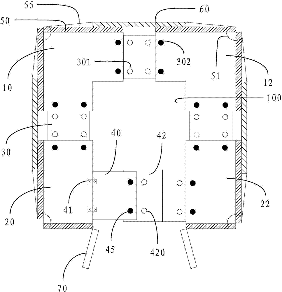
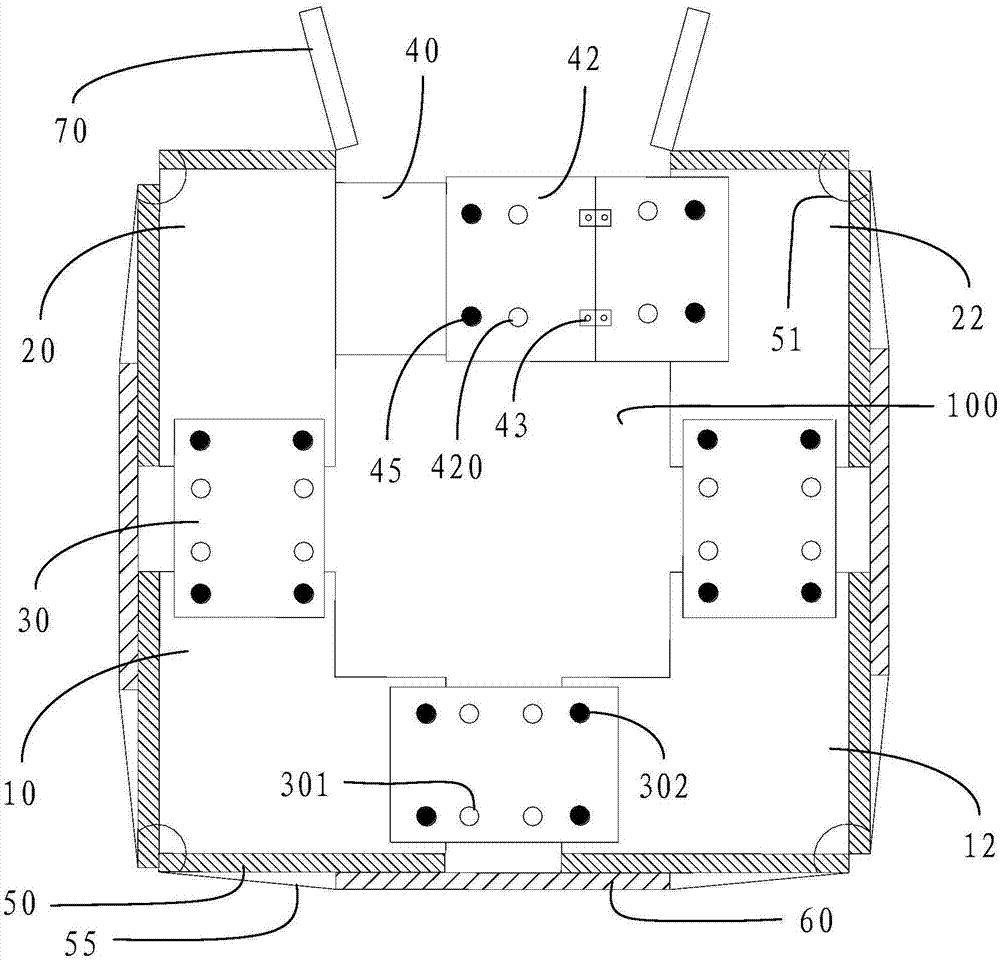
[0034] refer to figure 1 As shown, a plug-in type high-altitude welding platform of the present invention is sleeved on a steel column and is located around the steel column. The plate 12, the third plate 20 and the fourth plate 22, preferably, the first plate 10 and the second plate 12 are L-shaped. An adjustment slide plate 30 is connected between the first flat plate 10 and the second flat plate 12, an adjustment slide plate 30 is connected between the first flat plate 10 and the third flat plate 20, and the second flat plate 12 and the fourth flat plate 22 is connected with an adjustment slide plate 30; the third plate 20 is connected with an upper flap 40 on the side facing the fourth flat plate 22, and the fourth flat plate 22 is connected with a lower flap 42 on the side facing the third flat plate 20 , and the lower turning ...


PUM


Abstract

The invention discloses a drawing and inserting type aerial welding platform. The drawing and inserting type aerial welding platform is arranged on the periphery of a steel column and is in a rectangular shape. The drawing and inserting type aerial welding platform comprises a first flat plate, a second flat plate, a third flat plate and a fourth flat plate, all of which are located at the four corners of the welding platform. An adjusting sliding plate is connected between the third flat plate and the first flat plate, an adjusting sliding plate is connected between the first flat plate and the second flat plate, and an adjusting sliding plate is connected between the second flat plate and the fourth flat plate. An upper overturning plate and a lower overturning plate are connected between the third flat plate and the fourth flat plate. The adjusting sliding plates and the lower overturning plate are provided with a plurality of sets of connecting holes. According to a drawing and inserting type welding platform installing method, the first flat plate, the second flat plate, the third flat plate, the fourth flat plate, the upper overturning plate and the lower overturning plate are sequentially installed, and a hollow platform is formed and arranged on the periphery of the steel column in a sleeving manner from top to bottom and is fixed. According to the other drawing and inserting type welding platform installing method, the installed upper overturning plate and the installed lower overturning plate are overturned, a U-shaped platform is formed and then arranged on the periphery of the steel column in a sleeving manner from back to front, and the upper overturning plate and the lower overturning plate are restored and fixed.

Description

technical field [0001] The invention relates to the field of construction engineering, in particular to a plug-in high-altitude welding platform and an installation method thereof. Background technique [0002] With the continuous improvement of the country's economic strength and the continuous advancement of urbanization, high-rise and super high-rise buildings have become an indispensable business card for cities. Due to the unique advantages of steel structures in terms of construction speed, construction cost and mechanical performance, their application in high-rise and super high-rise projects is becoming more and more common. For high-rise buildings whose outer frame adopts steel structure, the high-altitude welding operation is frequent, and the psychological effect of high-altitude operation and the influence of high-altitude air flow have a non-negligible impact on the operation skills of welding operators. Therefore, as a welding quality control "person, Buildin...

Claims


Application Information

Patent Timeline
IPC IPC(8): B23K37/04
CPCB23K37/0461
Inventor 曹跃伟邹琪吴飞飞江章飞孙飞飞周封伟
Owner CHINA CONSTR EIGHT ENG DIV CORP LTD
Learn More